Toolbox

a toolbox and tool box technology, applied in the field of toolboxes, can solve the problems of inconvenient operation, increased costs, and prone to topple the toolbox, and achieve the effect of convenient engagement and positioning during operation

Inactive Publication Date: 2017-05-04
COMPASS
View PDF0 Cites 51 Cited by
  • Summary
  • Abstract
  • Description
  • Claims
  • Application Information

AI Technical Summary

Benefits of technology

[0005]An objective of the present invention is to provide a toolbox with fewer elements and permitting easy engagement and positioning during operation.

Problems solved by technology

However, a user has to carry many toolboxes when tools to be used are received in different toolboxes.
Although the toolboxes can be stacked to reduce the volume, the toolboxes are apt to topple over when the overall center of gravity becomes unstable during carriage.
However, the upper toolbox must be firstly placed on top of the lower toolbox before pivoting the hook to engage with the groove, which is inconvenient to operation.
Furthermore, the hook is a separate element pivotably mounted to the toolbox and, thus, increases the costs.

Method used


Image

  • Toolbox
  • Toolbox
  • Toolbox

Examples


Embodiment Construction

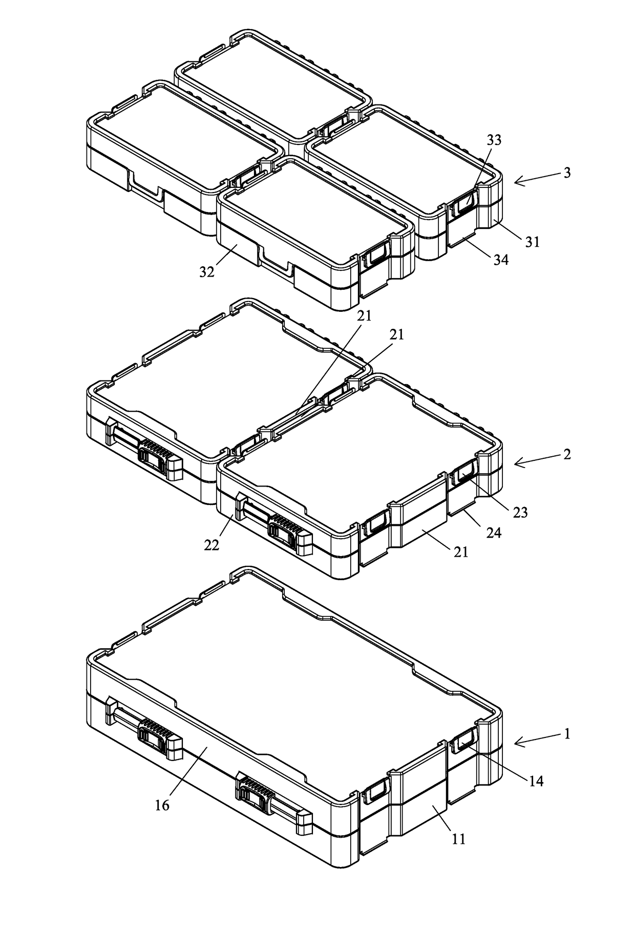
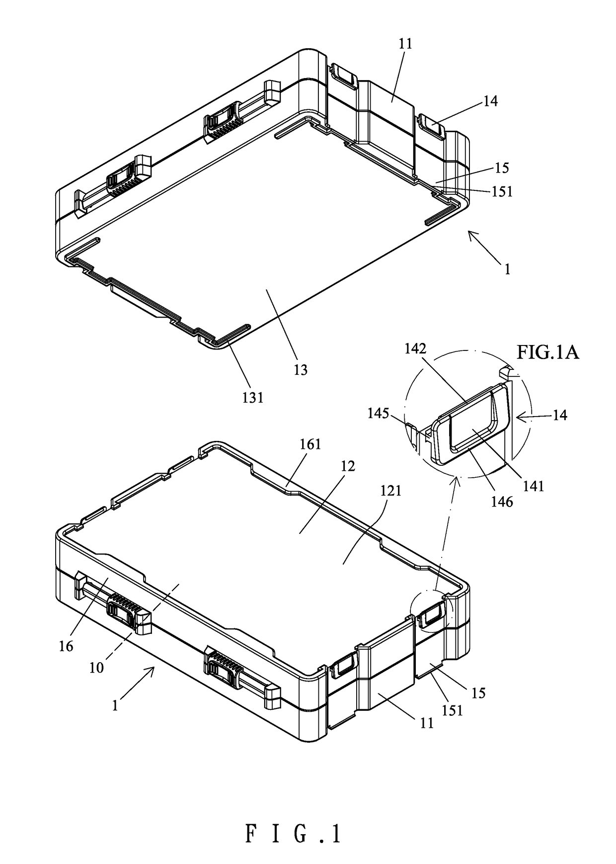
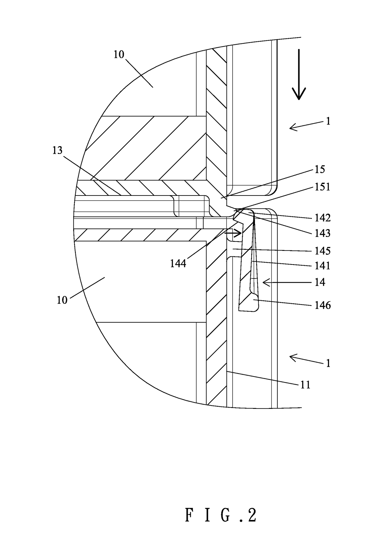
[0031]With reference to FIGS. 1 and 2, a first toolbox 1 according to the present invention is a parallelepiped and includes a space 10 for receiving tools. FIGS. 1 and 2 show two first toolboxes 1 of the same size. The first toolbox 1 includes two lateral sides 11 opposite to each other and two longitudinal sides 16 extending between the lateral sides 11. Each longitudinal side 16 has a length larger than a length of each lateral side 11. The first toolbox 1 further includes top and bottom sides 12 and 13. Each lateral side 11 includes two snap fasteners 14 on an upper end thereof and two engagement portions 15 on a lower end thereof. As shown in FIGS. 1A and 2, each snap fastener 14 includes an engagement plate 141. A hook 142 is formed on an upper end of the engagement plate 141 of each snap fastener 14 and protrudes towards a corresponding lateral side 11. The hook 142 of each snap fastener 14 includes a top having an inclined guiding face 143 and a bottom having a hooking face ...


PUM


Abstract

A toolbox includes a space for receiving tools and includes a peripheral side and top and bottom sides. The peripheral side includes at least one snap fastener on an upper end thereof and at least one engagement portion on a lower end thereof. The at least one snap fastener includes a flexible engagement plate. A hook is formed on an upper end of the engagement plate. The lower end of the engagement plate can be pressed to move the hook away from the peripheral side of the toolbox. The hook of the at least one snap fastener of the toolbox can engage with at least one engagement portion of another similarly constructed toolbox stacked above the toolbox. The at least one engagement portion of the toolbox can engage with a hook of at least one snap fastener of another similarly constructed toolbox stacked below the toolbox.

Description

BACKGROUND OF THE INVENTION[0001]The present invention relates to a toolbox and, more particularly, to a toolbox that can be stacked and positioned on another similarly constructed toolbox while reducing the elements and permitting easy engagement and positioning during operation.[0002]Similar tools are generally placed in the same toolbox for easy management, and tools of different types or sizes are placed in other toolboxes. However, a user has to carry many toolboxes when tools to be used are received in different toolboxes. Although the toolboxes can be stacked to reduce the volume, the toolboxes are apt to topple over when the overall center of gravity becomes unstable during carriage.[0003]To avoid the above disadvantage, a hook is pivotably mounted to a lateral side of the lower toolbox, and a groove for engaging with the hook is formed in a lateral side of the upper toolbox, such that the hook is engaged in the groove when the upper and lower toolboxes are stacked, preventi...

Claims


Application Information

Patent Timeline
Patent Type & Authority Applications(United States)
IPC IPC(8): B65D21/02
CPCB65D21/0204B65D21/0228B25H3/02B65D21/0219
Inventor WANG, TZU-CHIEN
Owner COMPASS
Why Eureka
Try Eureka