
Coaxial plug-in connector arrangement

a technology of coaxial plug-in connectors and connectors, which is applied in the direction of coupling devices, two-part coupling devices, electrical devices, etc., can solve the problems of adversely affecting the electrical transmission quality of coaxial plug-in connector arrangements, and achieve the effect of preventing penetration and simple design

Active Publication Date: 2017-05-11
TELEFON AB LM ERICSSON (PUBL)
View PDF6 Cites 10 Cited by
  • Summary
  • Abstract
  • Description
  • Claims
  • Application Information

AI Technical Summary

Benefits of technology

The coaxial plug-in connector arrangement described in this patent invention features an arresting element that fixes the inner sleeve in the outer sleeve and allows for easy detachment as needed. This reduces the risk of the inner sleeve moving and affecting the electrical transmission quality of the connector. Additionally, a spring element seals the annular space between the inner and outer sleeves, preventing moisture and dirt particles from entering. These features make the coaxial plug-in connector arrangement ideal for high-quality electrical performance.

Problems solved by technology

The arresting element thus reduces the risk of the inner sleeve moving relative to the outer sleeve after being inserted and thereby adversely affecting the electrical transmission quality of the coaxial plug-in connector arrangement.

Method used


Image

  • Coaxial plug-in connector arrangement
  • Coaxial plug-in connector arrangement
  • Coaxial plug-in connector arrangement

Examples


Embodiment Construction

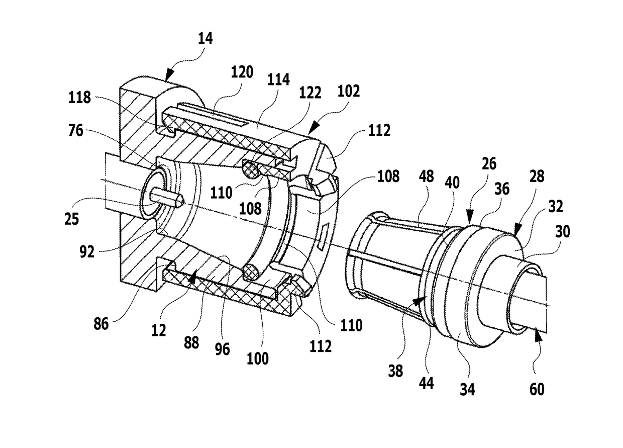
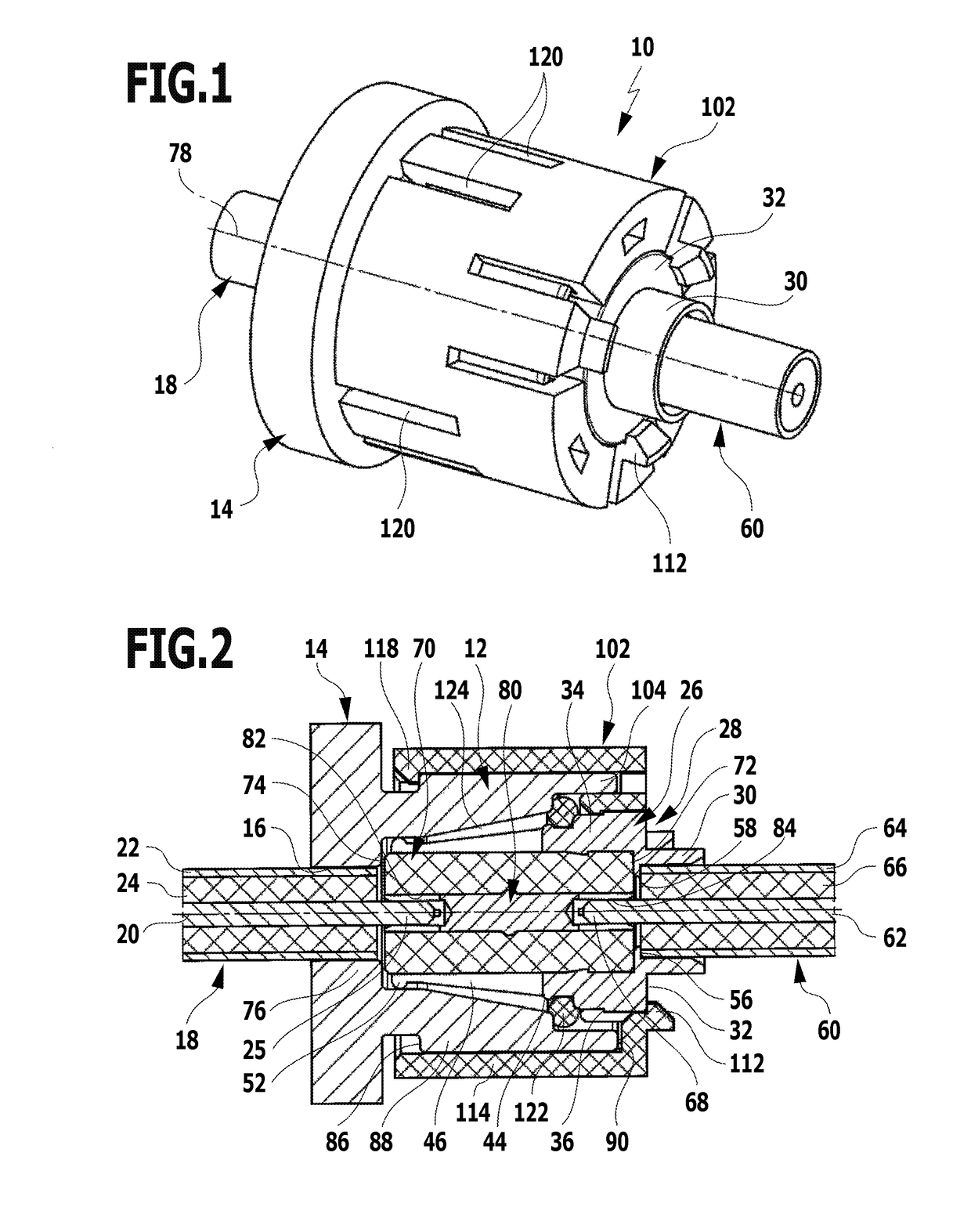
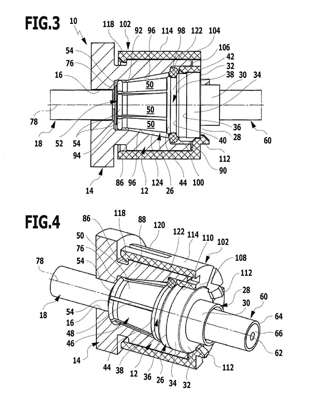
[0071]FIGS. 1 to 6 schematically illustrate a first advantageous embodiment of a coaxial plug-in connector arrangement, which is denoted overall by reference numeral 10. The coaxial plug-in connector arrangement 10 includes an outer sleeve 12, which is made of an electrically conductive material, in particular metal, and forms a socket housing 14 having a first through opening 16 into which a first coaxial cable 18 is inserted. The first coaxial cable 18 customarily has an inner conductor 20 and an outer conductor 22, between which a dielectric 24 is situated. The exposed outer conductor 22 is connected in an electrically conductive manner to the outer sleeve 12 in the region of the first through opening 16. In particular, it may be provided that the outer conductor 22 is soldered to the outer sleeve 12. The exposed inner conductor 20 protrudes into the outer sleeve 12 in the axial direction and forms a first contact pin 25.

[0072]In addition to the outer sleeve 12, the coaxial plug-...


PUM


Abstract

A coaxial plug-in connector arrangement is provided having an electrically conductive outer sleeve, and an electrically conductive inner sleeve which is insertable into the outer sleeve in the axial direction and is electrically connectable to the outer sleeve. A first contact pin is insertable into the outer sleeve from a side facing away from the inner sleeve. A second contact pin is insertable into the inner sleeve from a side facing away from the outer sleeve. An insulating part in which an inner conductor part is mounted is located in the inner sleeve. The two contact pins are connectable to one another in an electrically conductive manner via the inner conductor part. An arresting element is mountable on one of the two sleeves before insertion of the inner sleeve into the outer sleeve. The inner sleeve is detachably fixable in the outer sleeve by means of the arresting element.

Description

[0001]This application is a continuation of international application number PCT / EP2015 / 052070 filed on Feb. 2, 2015 and claims the benefit of German application number 10 2014 101 297.6 filed on Feb. 3, 2014, which are incorporated herein by reference in their entirety and for all purposes.BACKGROUND OF THE INVENTION[0002]The invention relates to a coaxial plug-in connector arrangement having an electrically conductive outer sleeve and an electrically conductive inner sleeve, which is insertable into the outer sleeve in the axial direction and is electrically connectable to the outer sleeve, a first contact pin being insertable into the outer sleeve from the side facing away from the inner sleeve, and a second contact pin being insertable into the inner sleeve from the side facing away from the outer sleeve, and an insulating part in which an inner conductor part is mounted being located in the inner sleeve, and the two contact pins being connectable to one another in an electrical...

Claims


Application Information

Patent Timeline
IPC IPC(8): H01R13/627H01R24/38
CPCH01R13/6275H01R2103/00H01R24/38H01R24/40
Inventor HAEGELE, WERNERBAECHLE, ERIKWAELLER, GUENTERBERGER, STEFANHAUNBERGER, THOMASGUENTHER, MARIOSTOLLE, MANFRED
Owner TELEFON AB LM ERICSSON (PUBL)
Learn More