Terminal apparatus and method for transmitting a response signal at a terminal
- Summary
- Abstract
- Description
- Claims
- Application Information
AI Technical Summary
Benefits of technology
Problems solved by technology
Method used
Image
Examples
embodiment 1
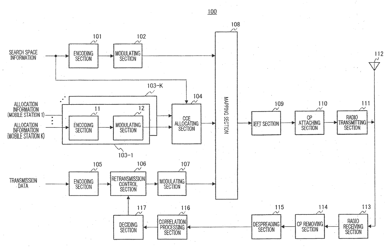
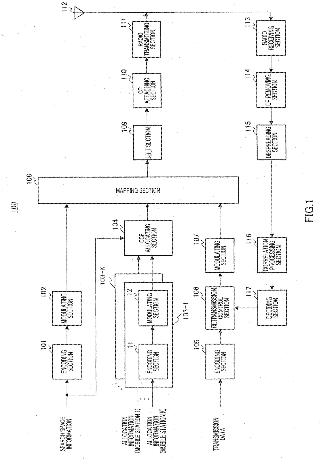
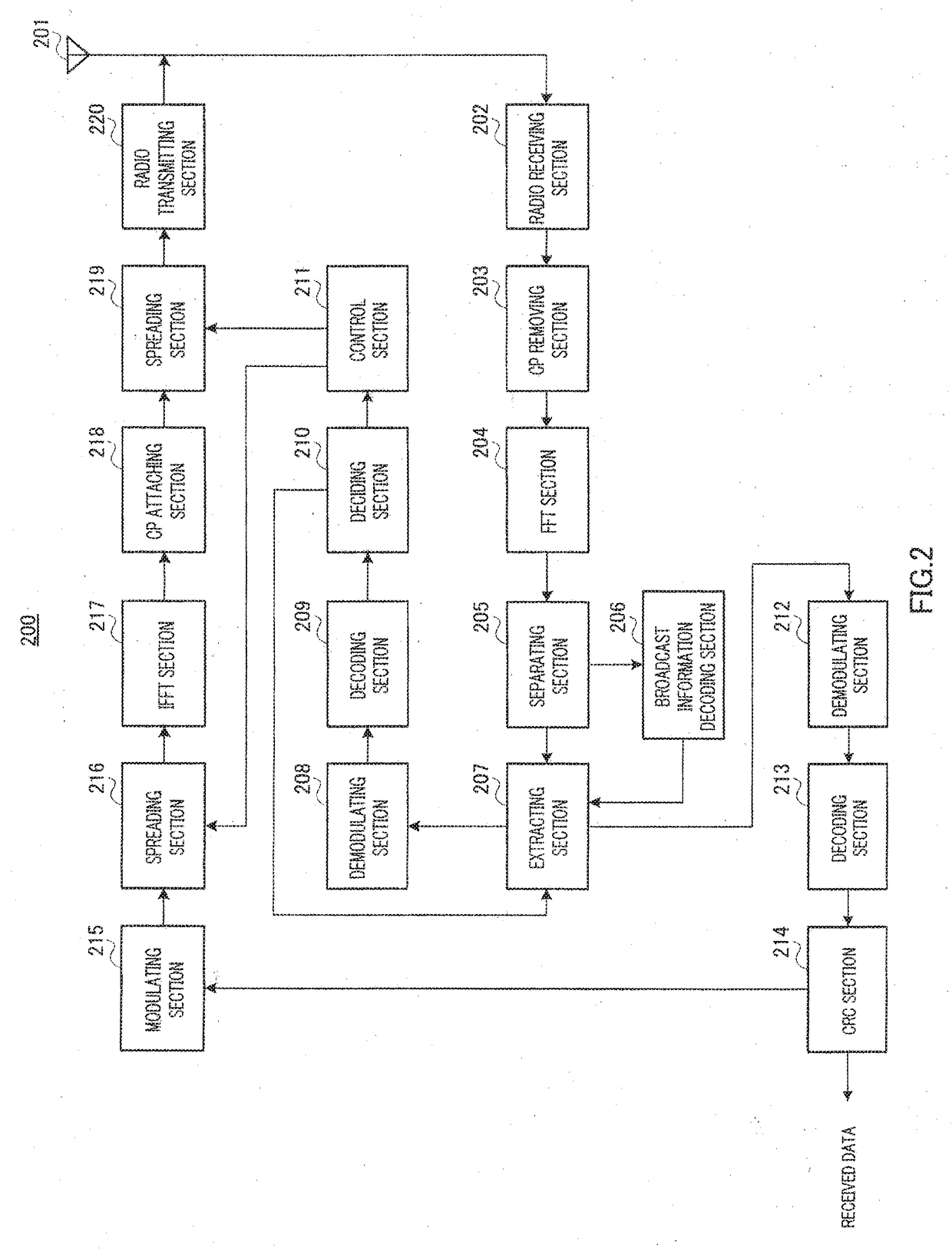
[0037]FIG. 1 shows the configuration of base station 100 according to the present embodiment, and FIG. 2 shows the configuration of mobile station 200 according to the present embodiment.
[0038]Here, to avoid complicated explanation, FIG. 1 shows components associated with transmission of downlink data and components associated with reception of uplink response signals to downlink data, which are closely related to the present invention, and the illustration and explanation of the components associated with reception of uplink data will be omitted. Similarly, FIG. 2 shows components associated with reception of downlink data and components associated with transmission of uplink response signals to downlink data, which are closely related to the present invention, and the illustration and explanation of the components associated with transmission of uplink data will be omitted.
[0039]In base station 100 shown in FIG. 1, encoding section 101 receives as input search space information in...
embodiment 2
[0095]In the search spaces shown in FIG. 4 of Embodiment 1, if an odd number of PDCCH's of a given CCE aggregation size are used, a CCE may arise which cannot be used as a PDCCH of a larger CCE aggregation size than the given CCE aggregation size.
[0096]For example, in the search spaces shown in FIG. 4, if five PDCCH's of a CCE aggregation size of 1 are used, CCE #0 to CCE #4 are occupied. In this case, out of PDCCH's of a CCE aggregation size of 2, the PDCCH formed with CCE #4 and CCE #5 cannot be used because CCE #4 is already used. That is, CCE #5 is not used. Similarly, for example, if three PDCCH's of a CCE aggregation size of 4 are used, CCE #8 to CCE #19 are occupied. In this case, out of PDCCH's of a CCE aggregation size of 8, the PDCCH formed with CCE #16 to CCE #23 cannot be used because CCE #16 to CCE #19 are already used. That is, CCE #20 to CCE #23 are not used. Thus, a part of CCE's forming a PDCCH is used by another PDCCH of a different CCE aggregation size, and, conse...
embodiment 3
[0104]A case will be explained with the present embodiment where downlink allocation information and uplink allocation information share a plurality of CCE's.
[0105]The method of allocating CCE's in the present embodiment will be explained.
[0106]
[0107]With the present embodiment, in a plurality of CCE's forming a specific search space, downlink allocation information for notifying a downlink allocation result is allocated in ascending order from the CCE of the lowest CCE number, and uplink allocation information for notifying an uplink allocation result is allocated in descending order from the CCE of the highest CCE number.
[0108]This will be explained below in detail. Here, the same search spaces as those in FIG. 8 of Embodiment 2 will be used. Also, the above will be explained focusing on the case where the CCE aggregation size is 1.
[0109]As shown in FIG. 9, in the search space (CCE's #22 to #31) matching a CCE aggregation size of 1, CCE allocating section 104 allocates downlink al...
PUM
 Abstract
Description
Claims
Application Information
 - R&D
- Intellectual Property
- Life Sciences
- Materials
- Tech Scout
- Unparalleled Data Quality
- Higher Quality Content
- 60% Fewer Hallucinations
Browse by: Latest US Patents, China's latest patents, Technical Efficacy Thesaurus, Application Domain, Technology Topic, Popular Technical Reports.
© 2025 PatSnap. All rights reserved.Legal|Privacy policy|Modern Slavery Act Transparency Statement|Sitemap|About US| Contact US: help@patsnap.com


