
Process display system, display terminal, process management apparatus, and non-transitory computer readable medium

Active Publication Date: 2021-03-04
FUJIFILM BUSINESS INNOVATION CORP
View PDF0 Cites 0 Cited by
  • Summary
  • Abstract
  • Description
  • Claims
  • Application Information

AI Technical Summary

Benefits of technology

The patent text is about a system, a device, a system management tool, and a computer-readable medium that can decrease the number of times a display terminal updates its display. The technical effect of this invention is to improve the efficiency and reduce the burden on the display terminal, which can improve the overall user experience.

Problems solved by technology

However, display terminals have limited resources in comparison with general personal computers (PCs), and some display terminals operate slowly when display is updated.
Accordingly, updating information display on each display terminal every time the information is changed makes it difficult to manage the process smoothly.
However, aspects of the non-limiting embodiments are not required to address the advantages described above, and aspects of the non-limiting embodiments of the present disclosure may not address advantages described above.

Method used


Image

  • Process display system, display terminal, process management apparatus, and non-transitory computer readable medium
  • Process display system, display terminal, process management apparatus, and non-transitory computer readable medium
  • Process display system, display terminal, process management apparatus, and non-transitory computer readable medium

Examples


first exemplary embodiment

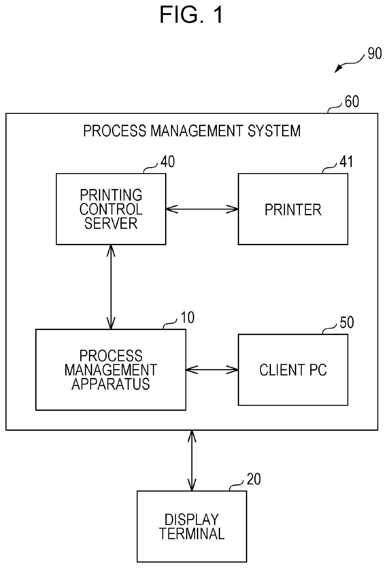
[0019]FIG. 1 is a diagram illustrating an example configuration of a process display system 90 according to a first exemplary embodiment.

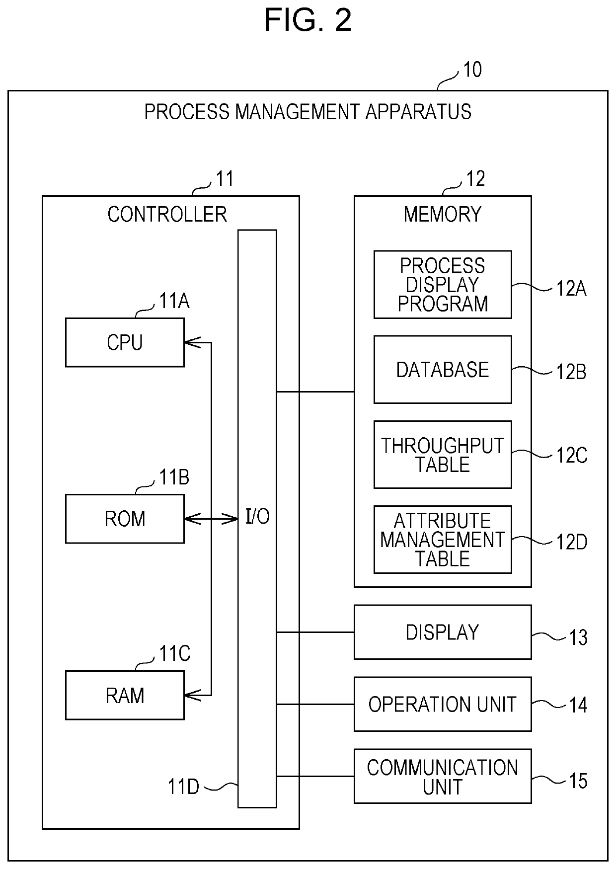
[0020]As illustrated in FIG. 1, the process display system 90 according to this exemplary embodiment includes a process management system 60 and a display terminal 20. The process management system 60 includes a process management apparatus 10, a printing control server 40, a printer 41, and a client PC 50. The process management system 60 has the process management apparatus 10 as a cloud server and provides a process management service to a user of the client PC 50 with a cloud system. However, the process management service is not limited to a cloud service and may be an on-premise service. This exemplary embodiment is described by taking a printing process as an example of a process to be managed. The term “printing process” herein denotes a process from the production of a printed material to shipping, specifically, a process including receivi...

second exemplary embodiment

[0069]In the description of the first exemplary embodiment above, the process management system 60 including the process management apparatus 10 mainly performs the processing, and the number of times the display on the display terminal 20 is updated is reduced. In contrast, in the description for a second exemplary embodiment, the display terminal 20 mainly performs the processing, and the number of times the display on the display terminal 20 is updated is reduced.

[0070]FIG. 6 is a block diagram illustrating an example electrical configuration of the display terminal 20 according to the second exemplary embodiment. FIG. 6 illustrates an MR device that applies to the display terminal 20. However, as described above, a VR device or an AR device may be applied.

[0071]As illustrated in FIG. 6, the display terminal 20 according to this exemplary embodiment includes a controller 21, a memory 22, a display 23, an imaging unit 24, and a communication unit 25.

[0072]The controller 21 include...


PUM


Abstract

A process display system includes a display terminal including a first processor and a process management system that includes a second processor and that communicates with the display terminal. The first processor or the second processor performs control of whether to update display of process information regarding a process. The process information is displayed by the display terminal. The control is performed on a basis of a change level of the process information on the display terminal.

Description

CROSS-REFERENCE TO RELATED APPLICATIONS[0001]This application is based on and claims priority under 35 USC 119 from Japanese Patent Application No. 2019-158716 filed Aug. 30, 2019.BACKGROUND(i) Technical Field[0002]The present disclosure relates to a process display system, a display terminal, a process management apparatus, and a non-transitory computer readable medium.(ii) Related Art[0003]For example, Japanese Unexamined Patent Application Publication No. 2018-181232 describes a maintenance support apparatus that extracts operating states of factory facilities and that displays, on a head mounted display including a display and an imaging unit, maintenance information for a factory facility judged to have an abnormality occurrence. The display displays an augmented reality image in which an additional image is superimposed on the real scene. The imaging unit captures the image of the real scene and acquires a real image. The maintenance support apparatus includes an image analysi...

Claims


Application Information

Patent Timeline
IPC IPC(8): G02B27/01G06K9/00G06T7/00
CPCG02B27/017G06K9/00671G06T2207/30164G02B2027/0138G02B2027/0141G06T7/0004G06F3/011G06Q10/06316G02B2027/014G06F3/1207G06F3/121G06F3/1229G06F3/1259G06F3/1288G06F3/1292G06V20/20
Inventor SUZUKI, KODAIKANZAKI, AMIARAKAWA, KEI
Owner FUJIFILM BUSINESS INNOVATION CORP
Learn More