Liquid jetting apparatus

a technology of liquid jetting apparatus and nozzle, which is applied in printing and other directions, can solve the problems of destroying the ink meniscus in the nozzle, the nozzle cap spilling, etc., and achieves the effect of reducing the time required for the movement of the head cap

Active Publication Date: 2017-05-18
BROTHER KOGYO KK
View PDF4 Cites 3 Cited by
  • Summary
  • Abstract
  • Description
  • Claims
  • Application Information

AI Technical Summary

Benefits of technology

[0005]Regarding Japanese Patent No. 5056465, movement speed of the head cap in a direction perpendicular to the nozzle forming surface increases as the inclined angles of the first and second inclined cam surfaces relative to the carriage movement direction are greater. This reduces the time required for movement of the head cap. In this case, the mo

Problems solved by technology

This may cause an ink spill from the nozzle cap and the destruction of ink meniscu

Method used


Image

  • Liquid jetting apparatus
  • Liquid jetting apparatus
  • Liquid jetting apparatus

Examples


Embodiment Construction

[0052]Preferred embodiments of the present teaching will be described below.

[0053]

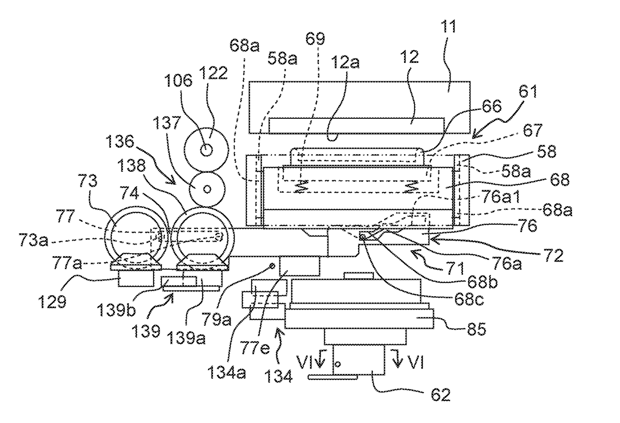
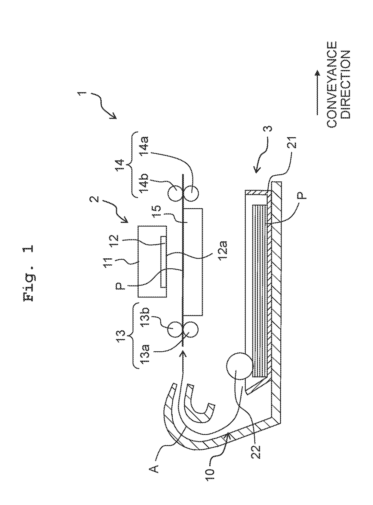
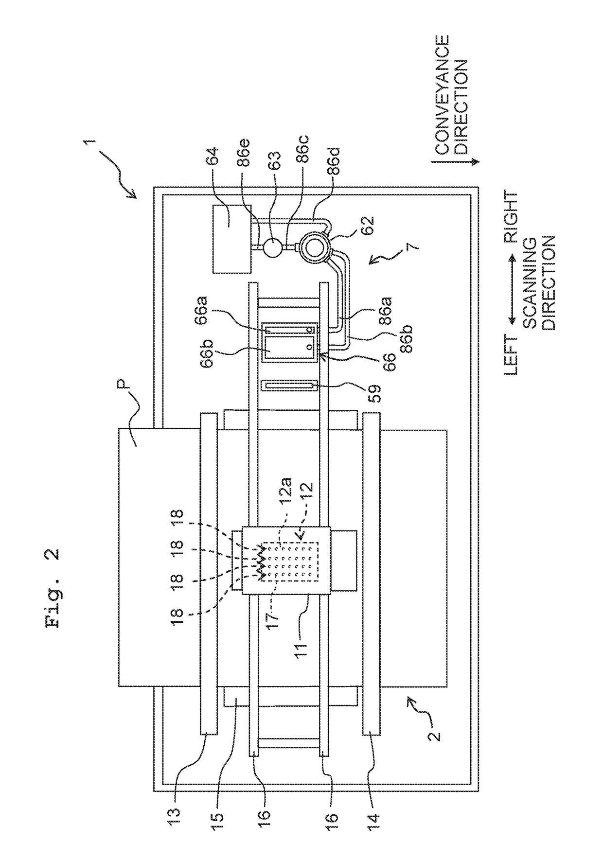
[0054]As depicted in FIGS. 1 and 2, a printer 1 of this embodiment (a “liquid jetting apparatus” of the present teaching) includes, for example, a printing unit 2, a feed part 3, and a maintenance unit 7.

[0055]

[0056]The printing unit 2 includes, for example, a carriage 11, an ink-jet head 12 (a “liquid jetting head” of the present teaching), conveyance rollers 13, 14, and a platen 15. The carriage 11 is movably supported in a scanning direction by two guide rails 16 extending in the scanning direction. The carriage 11, which is connected to a carriage motor 156 (see FIG. 14) via an unillustrated belt and pulley, is driven by the carriage motor 156 so as to reciprocate in the scanning direction. In the following, the right and the left in the scanning direction are defined as indicated in FIG. 2.

[0057]The ink-jet head 12, which is carried on the carriage 11, jets an ink from nozzles 17 formed in an ink ...


PUM


Abstract

A liquid jetting apparatus includes: a head unit including nozzles; a cap which covers the nozzles in a state of being in contact with the head unit at a capping position; and a cap movement device including a cam having a slide surface and a cam follower which is slid on the slide surface. One of the cam and the cam follower is provided integrally with the cap, and the other of the cam and the cam follower is moved in a slide direction. The slide surface includes a first inclined surface inclined by a first angle relative to the slide direction and a second inclined surface inclined by a second angle greater than the first angle relative to the slide direction.

Description

CROSS REFERENCE TO RELATED APPLICATION[0001]The present application claims priority from Japanese Patent Application No. 2015-1816 filed on Nov. 12, 2015, the disclosure of which is incorporated herein by reference in its entirety.BACKGROUNDField of the Invention[0002]The present invention relates to a liquid jetting apparatus configured to jet liquid from nozzles.Description of the Related Art[0003]As an exemplary liquid jetting apparatus jetting liquid from nozzles, Japanese Patent No. 5056465 describes a printing apparatus which jets ink from nozzles to perform printing. The printing apparatus described in Japanese Patent No. 5056465 includes a head cap mechanism. The head cap mechanism includes a slider, a cap holder, a head cap, and a cam mechanism. The slider is provided in a housing to be slidable in a carriage movement direction. The cap holder is slidably provided in the slider to be closer to or away from a printing head. The head cap is fixed to the cap holder. The cam me...

Claims


Application Information

Patent Timeline
IPC IPC(8): B41J2/165
CPCB41J2/16511B41J2/16532B41J2002/16573B41J2002/16514B41J2/16523B41J2/16508
Inventor OGAWA, MIKIO
Owner BROTHER KOGYO KK
Why Eureka
Try Eureka