
Multi-antenna relay device

a relay device and multi-antenna technology, applied in the field of multi-antenna relay devices, can solve the problems of difficult to appropriately cope and increase the number of transmitting/receiving antennas, and achieve the effects of reducing signal interference and oscillation, reducing interference signals, and reducing interference and oscillation

Active Publication Date: 2017-05-18
SOLID
View PDF6 Cites 2 Cited by
  • Summary
  • Abstract
  • Description
  • Claims
  • Application Information

AI Technical Summary

Benefits of technology

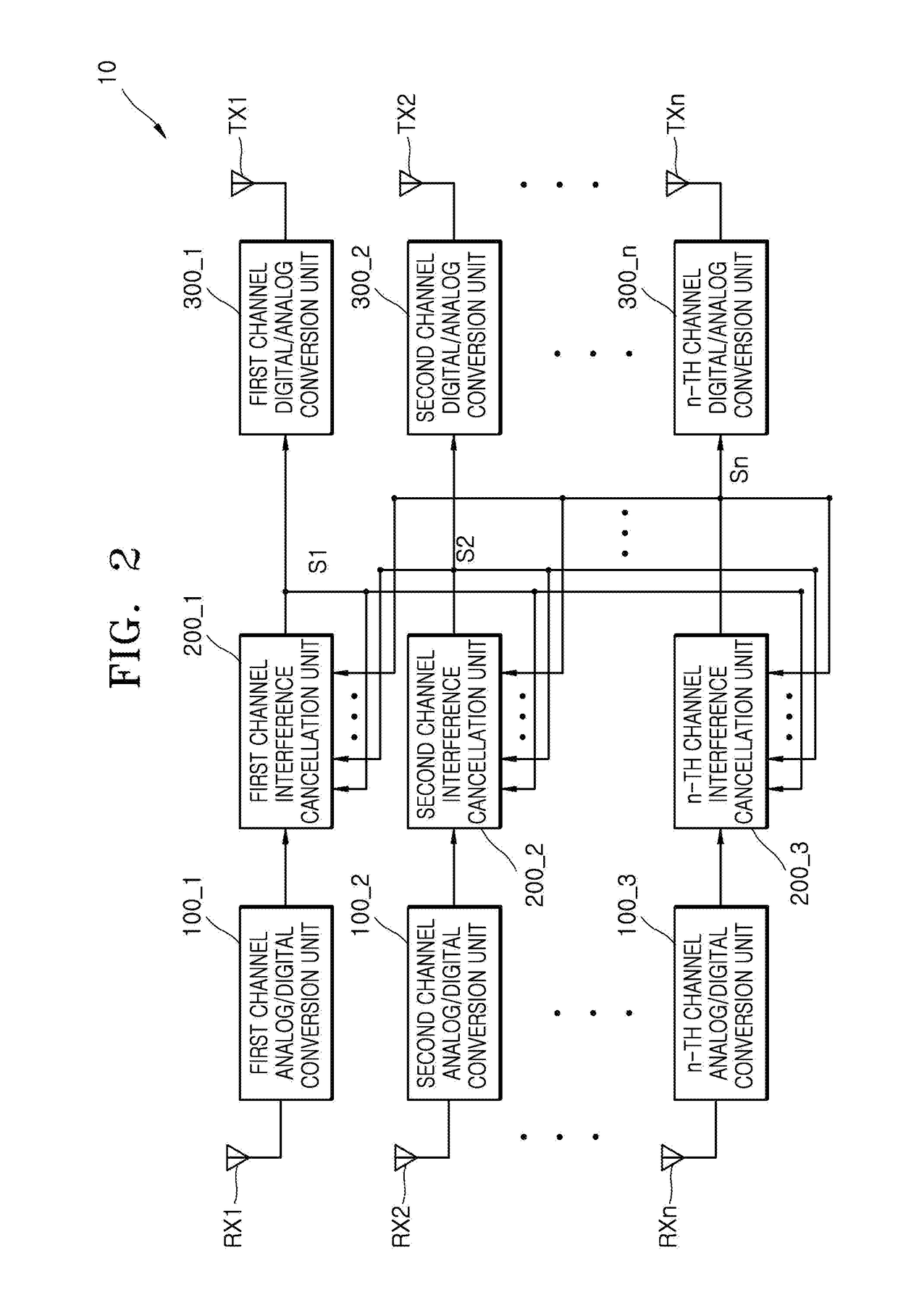
The patent describes a device that uses multiple antennas to cancel out interference signals in real-time, to improve transmission rate and quality of communication services while minimizing signal interference and oscillation. The device includes an interference cancellation unit for each channel, which can quickly cancel out interference signals from all channels. Overall, the device provides better performance and a better user experience in wireless communication.

Problems solved by technology

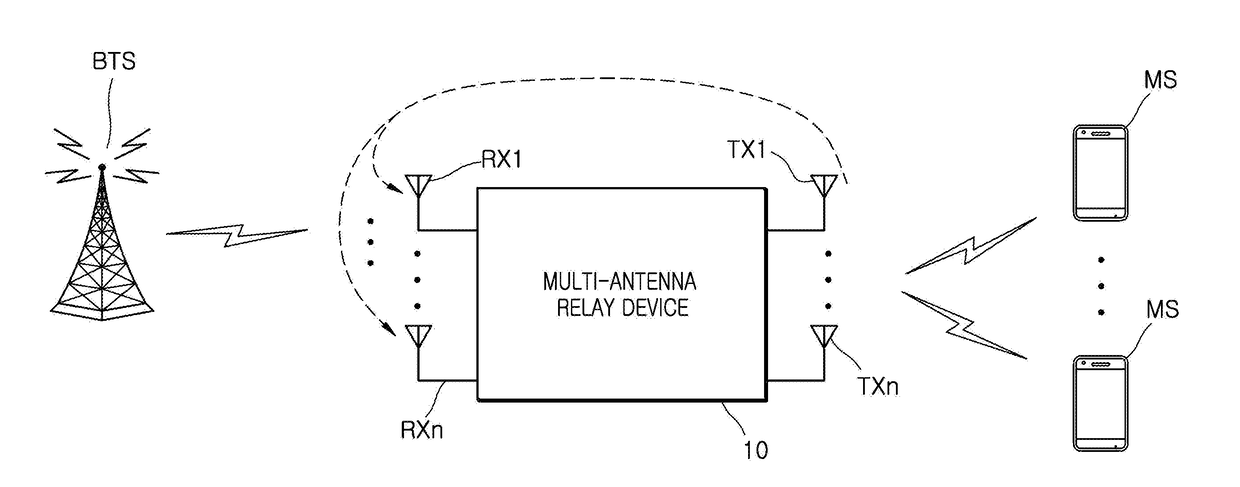
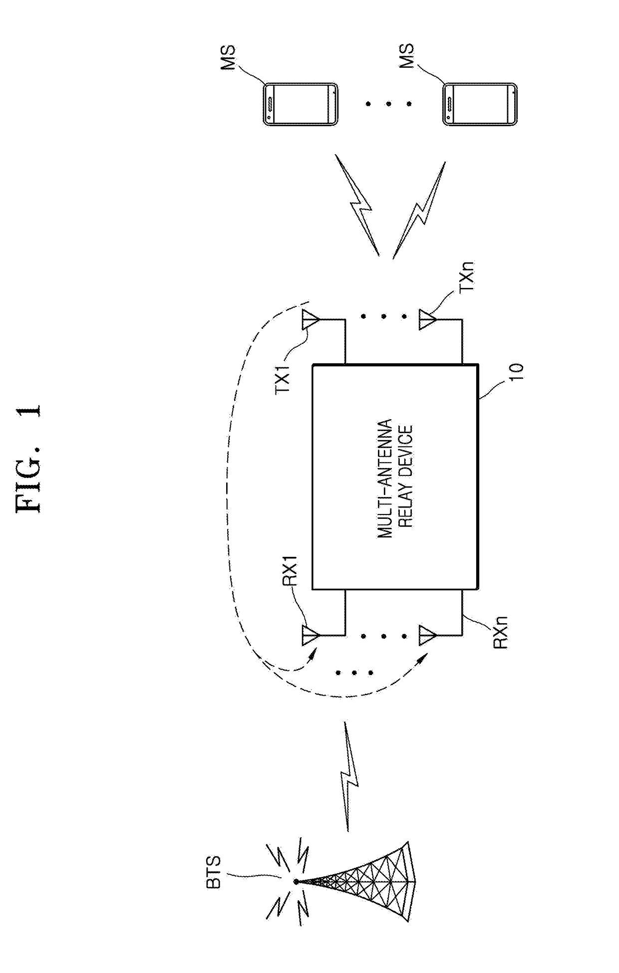
However, the wireless relay device adopting the multi-transmitting / receiving antenna (hereinafter, referred to as multi-antenna relay device) has a problem in that the number of transmitting / receiving antennas increases, feedback signals, that is, signals input into multiple receiving antennas as interference signals through a variety of paths, after the signals radiated from the transmitting antenna, significantly increase, and as a result, it is difficult to appropriately cope with a problem of interference in connection with an original signal and an oscillation problem.

Method used


Image

  • Multi-antenna relay device
  • Multi-antenna relay device
  • Multi-antenna relay device

Examples


Embodiment Construction

[0029]Hereinafter, embodiments of the inventive concept will be described in detail with reference to the accompanying drawings. Like reference numerals refer to like elements in the drawings and a duplicated description of like elements will be skipped.

[0030]Embodiments of the inventive concept are provided to more completely describe the inventive concept to those skilled in the art and various modifications of the embodiments described below can be made and the scope of the inventive concept is not limited to the embodiments described below. Still, the embodiment is provided to make the present disclosure be more substantial and complete and completely transfer the spirit of the inventive concept to those skilled in the art.

[0031]In describing the embodiments of the inventive concept, detailed description of associated known function or constitutions will be omitted if they make the gist of the inventive concept unclear. In addition, numeral figures (for example, 1, 2, and the li...


PUM


Abstract

Provided is a multi-antenna relay device. The multi-antenna relay device having first to n-th (n is a natural number of 2 or more) channel formed between receiving antennas and transmitting antennas corresponding to each other, comprising: first to n-th channel interference cancellation units, respectively, included in a corresponding channel among the first to n-th channels and canceling first to n-th channel interference signals corresponding to signals radiated through the first to n-th channels from signal input into the corresponding channel in real time.

Description

CROSS REFERENCE TO RELATED APPLICATIONS[0001]This application is a National Stage of International Application No. PCT / KR2014 / 003068, filed Apr. 9, 2014, and claims priority from Korean Patent Applications No. 10-2014-0041293 filed Apr. 7, 2014, the contents of which are incorporated herein by reference in their entireties.BACKGROUND[0002]1. Field[0003]The inventive concept relates to a multi-antenna relay device, and particularly, to a multi-antenna relay device which can cancel feedback signals due to signals radiated through multiple transmitting antennas in real time.[0004]2. Description of Related Art[0005]In general, a relay device is used for transmitting a signal between a base station and a terminal and service extension or improvement of a service quality in a radio signal shadow area. As one example of the relay device, a wireless relay device may be provided and the wireless relay device provides a communication service for receiving the signal transmitted from the base ...

Claims


Application Information

Patent Timeline
Patent Type & Authority Applications(United States)
IPC IPC(8): H04B7/155
CPCH04B7/15585H04B7/15507
Inventor KIM, HYUNCHAE
Owner SOLID
Learn More