Intake air temperature estimation system for turbocharged engine

a turbocharged engine and intake air temperature technology, applied in the direction of heat measurement, electric control, instruments, etc., can solve the problems of inability to accurately estimate the inability to respond to a change in the intake air temperature with respect to a change in the intake air, and the enormous amount of time and effort required to construct such a physical model. , to achieve the effect of accurate estimation of the intake air temperature, simple computation and high followability

Inactive Publication Date: 2018-04-24
TOYOTA JIDOSHA KK
View PDF6 Cites 0 Cited by
  • Summary
  • Abstract
  • Description
  • Claims
  • Application Information

AI Technical Summary

Benefits of technology

[0010]The embodiment provides an intake air temperature estimation system for a turbocharged engine, which is able to accurately estimate an intake air temperature after compression by a compressor through a simple computation.
[0014]In this regard, the estimated intake air temperature computing unit in the intake air temperature estimation system for a turbocharged engine variably sets a coefficient of the function in response to an amount of change per unit time in the intake air pressure after compression such that a followability of the estimated intake air temperature to the adiabatically compressed intake air temperature at the time when the amount of change is large is higher than a followability of the estimated intake air temperature to the adiabatically compressed intake air temperature at the time when the amount of change is small. A delay of the estimated intake air temperature computed in this way from the adiabatically compressed intake air temperature is small when the amount of change per unit time in the intake air pressure after compression is large, that is, when a change in the intake air pressure after compression is steep. The delay from the adiabatically compressed intake air temperature is large when the amount of change per unit time in the intake air pressure after compression is small, that is, when a change in the intake air pressure after compression is gentle. Therefore, as well as the above-described actual intake air temperature after compression, the manner of a delay of the estimated intake air temperature that is computed by the estimated intake air temperature computing unit in this way from the adiabatically compressed intake air temperature varies depending on whether a change in the intake air pressure after compression is steep or gentle. In addition, the function that is used by the estimated intake air temperature computing unit for computation is a simple one that expresses a first-order lag model, and the coefficient of the function is just changed commensurately with a steep or gentle change in the intake air pressure after compression. Therefore, with the intake air temperature estimation system for a turbocharged engine, it is possible to accurately estimate the intake air temperature after compression by the compressor through a simple computation.
[0015]Incidentally, since the intake air temperature after compression changes with a delay from the intake air pressure after compression as described above, a change in the intake air temperature after compression with a change in the intake air pressure after compression continues even after the change in the intake air pressure after compression has converged. For this reason, if the followability of the estimated intake air temperature to the adiabatically compressed intake air temperature is immediately decreased at the time when the amount of change per unit time in the intake air pressure after compression reduces, a change in the estimated intake air temperature can delay more than a change in the actual intake air temperature after compression. In contrast, the estimated intake air temperature computing unit in the intake air temperature estimation system for a turbocharged engine may, when the coefficient changes with a reduction in the amount of change per unit time in the intake air pressure after compression, compute the estimated intake air temperature while executing a guard process, the guard process being a process of limiting the amount of change per unit time in the coefficient to a prescribed guard value or lower. When such a guard process is executed, the high followability of the estimated intake air temperature to the adiabatically compressed intake air temperature continues for a while even after a steep change in the intake air pressure after compression has converged. Therefore, it is possible to reduce the above-described delay of the estimated intake air temperature.
[0016]If the limitations on the change in the coefficient are continued even after the change in the intake air pressure after compression has converged as a result of the above-described guard process, the computed estimated intake air temperature can converge to a value after the change in the intake air pressure after compression earlier than the actual intake air temperature after compression. In this case, the estimated intake air temperature computing unit may execute the guard process by setting a guard value such that the guard value at the time when the amount of change per unit time in the intake air pressure after compression is large is smaller than the guard value at the time when the mount of change is small. With this configuration, the change in the intake air pressure after compression proceeds toward convergence, and limitations on the amount of change in the coefficient through the guard process are more relaxed as the amount of change per unit time in the intake air pressure after compression reduces. For this reason, it is possible to more quickly cancel limitations on the amount of change in the coefficient through the guard process in response to convergence of a change in the intake air pressure after compression.

Problems solved by technology

Incidentally, actual compression of intake air in the compressor is not performed in an adiabatic state, and there is a delay in response of a change in the intake air temperature with respect to a change in the intake air pressure after compression due to, for example, heat exchange with external parts (intake pipe, and the like).
However, in the existing intake air temperature estimation system for a turbocharged engine, the influence of heat exchange with such external parts is not taken into consideration, so there is a concern about an error in an estimated intake air temperature during the transition.
However, an extremely enormous amount of time and effort are required to construct such a physical model, and a massive amount of computations are required to estimate the intake air temperature with the use of such a physical model.
That is, a delay of the intake air temperature after compression from the adiabatically compressed intake air temperature is small when a change in the intake air pressure after compression is steep, and the delay is large when a change in the intake air pressure after compression is gentle.
Therefore, the delay cannot be simply expressed as a first-order lag model.
A delay of the estimated intake air temperature computed in this way from the adiabatically compressed intake air temperature is small when the amount of change per unit time in the intake air pressure after compression is large, that is, when a change in the intake air pressure after compression is steep.
On the other hand, generally, an increase in the intake air pressure after compression at the time of acceleration of the turbocharged engine takes more time than a decrease in the intake air pressure after compression at the time of deceleration of the turbocharged engine, so a steep change in the intake air pressure after compression is hard to occur at the time of an increase in the intake air pressure after compression where the intake air temperature after compression rises.

Method used


Image

  • Intake air temperature estimation system for turbocharged engine
  • Intake air temperature estimation system for turbocharged engine
  • Intake air temperature estimation system for turbocharged engine

Examples


Embodiment Construction

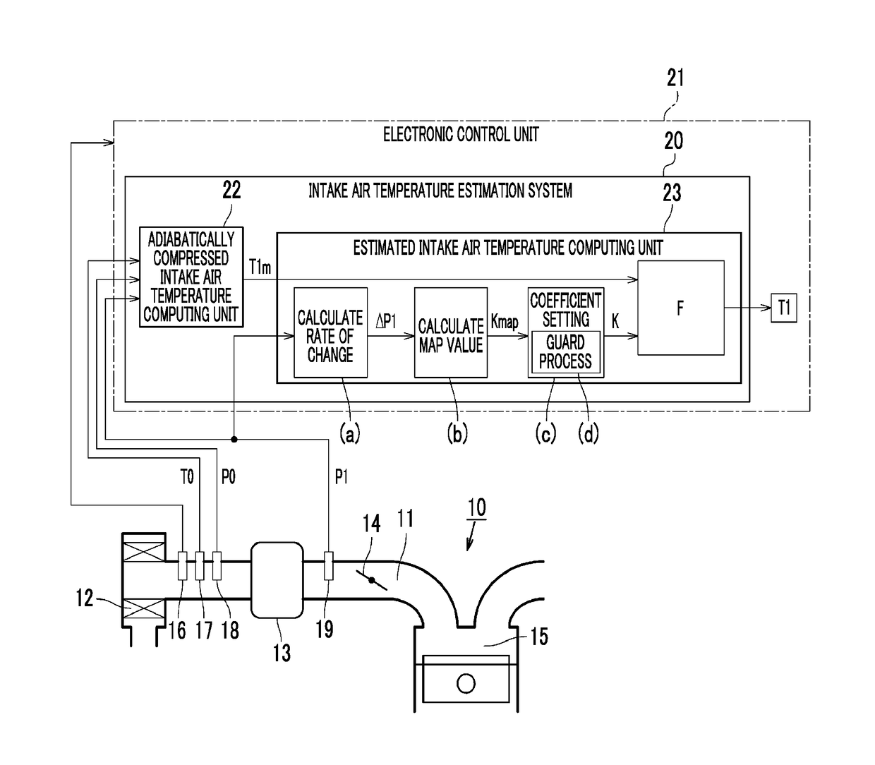
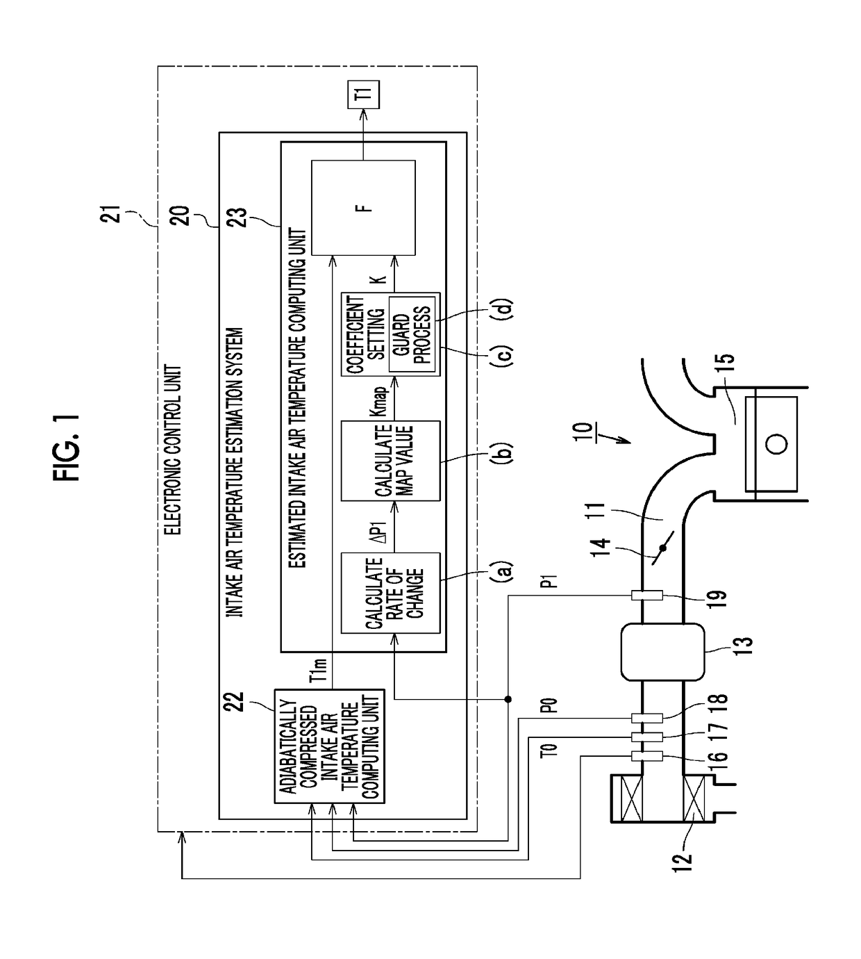
[0032]Hereinafter, an embodiment of an intake air temperature estimation system for a turbocharged engine will be described in detail with reference to FIG. 1 to FIG. 8. As shown in FIG. 1, an air cleaner 12 is provided in an intake passage 11 of the turbocharged engine 10. The intake air temperature estimation system 20 according to the present embodiment is applied to the turbocharged engine 10. The air cleaner 12 filters impurities, such as dust, contained in intake air that is taken into the intake passage 11. A compressor 13 is provided in the intake passage 11 at a portion downstream of the air cleaner 12. The compressor 13 is driven by the rotation of a turbine wheel, caused by the stream of exhaust gas from the turbocharged engine 10, or the rotation of a crankshaft that is the output shaft of the turbocharged engine 10 to compress intake air and discharge the compressed intake air to the downstream side of the intake passage 11. A throttle valve 14 is further provided in th...


PUM

PropertyMeasurementUnit
temperatureaaaaaaaaaa
pressureaaaaaaaaaa
volume flow rateaaaaaaaaaa

Abstract

An intake air temperature estimation system includes: an adiabatically compressed intake air temperature computing unit that computes an adiabatically compressed intake air temperature based on an intake air temperature before compression, an intake air pressure before compression and an intake air pressure after compression; and an estimated intake air temperature computing unit that computes an estimated intake air temperature. The estimated intake air temperature computing unit variably sets a coefficient of the function in response to an amount of change per unit time in the intake air pressure after compression such that a followability of the estimated intake air temperature to the adiabatically compressed intake air temperature at the time when the amount of change is large is higher than a followability of the estimated intake air temperature to the adiabatically compressed intake air temperature at the time when the amount of change is small.

Description

INCORPORATION BY REFERENCE[0001]The disclosure of Japanese Patent Application No. 2016-026873 filed on Feb. 16, 2016 including the specification, drawings and abstract is incorporated herein by reference in its entirety.BACKGROUND[0002]1. Technical Field[0003]The embodiment relates to an intake air temperature estimation system that is applied to a turbocharged engine including a compressor that compresses intake air and supplies the compressed intake air to a combustion chamber and that estimates the temperature of intake air after compression by the compressor.[0004]2. Description of Related Art[0005]Most of engines, such as vehicle-mounted engines, are provided with an air flow meter and an outside air temperature sensor. The air flow meter detects the volume flow rate of intake air in an intake passage. The outside air temperature sensor detects the temperature of outside air taken into the intake passage. The mass of intake air introduced into a combustion chamber, that is, the...

Claims


Application Information

Patent Timeline
Patent Type & Authority Patents(United States)
IPC IPC(8): F02D41/00F02D41/26G01K13/02F02D41/14
CPCF02D41/0007F02D41/26G01K13/02F02D2041/1422Y02T10/144F02D2200/0406F02D2200/0416G01K2205/02F02D2041/1432F02D23/00F02D41/1401F02D2200/0414Y02T10/12
Inventor KAMISHIMA, HIROFUMI
Owner TOYOTA JIDOSHA KK
Why Eureka
Try Eureka