Partial float weave fabric

Active Publication Date: 2017-05-25
MILLIKEN & CO
View PDF5 Cites 24 Cited by
  • Summary
  • Abstract
  • Description
  • Claims
  • Application Information

AI Technical Summary

Benefits of technology

[0006]An innerduct for a cable, comprising one or more strip-shaped lengths of the woven textile fab

Problems solved by technology

However, it has been found that it is difficult to merely insert a second cable into a conduit that already contains a first cable.
When a rope is blown or “snaked” into a conduit already containing a cable (or when a second cable is “

Method used


Image

  • Partial float weave fabric
  • Partial float weave fabric
  • Partial float weave fabric

Examples


example 1

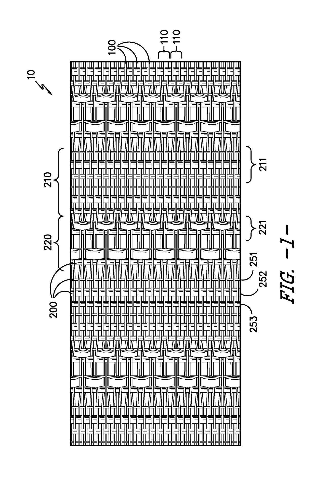
[0060]A textile fabric (shown in FIG. 1) having the following characteristics was woven on a Dornier HTVS 4 / S 220 cm machine:

[0061]Warp: 48 ends per inch of 520d denier PET monofilament yarn;

[0062]Filling: 18 picks per inch, in a 3 pick repeat (Total repeat of design is 18)[0063](1) 350 denier nylon 6 monofilament yarn;[0064](2) double insertion of 681 denier textured PET multifilament yarn (two-ply 300 denier / 68 filaments;[0065](3) single insertion of 681 denier textured PET multifilament yarn (two-ply 300 denier / 68 filaments;

[0066]The first weave zones were a plain weave containing 2 full sets of the pick repeat. The warp yarns were organized into groups of three with the inner yarn floating and the outer 2 yarns forming a plain weave stitch. The floating yarn floated over the double-inserted yarns (#2 from above) in each repeat of the pick repeat pattern. The partial float zones contained 2 full sets of the pick repeats. The fabric had a warp tensile of 265 lbs / in and a 4×8 filli...

example 2

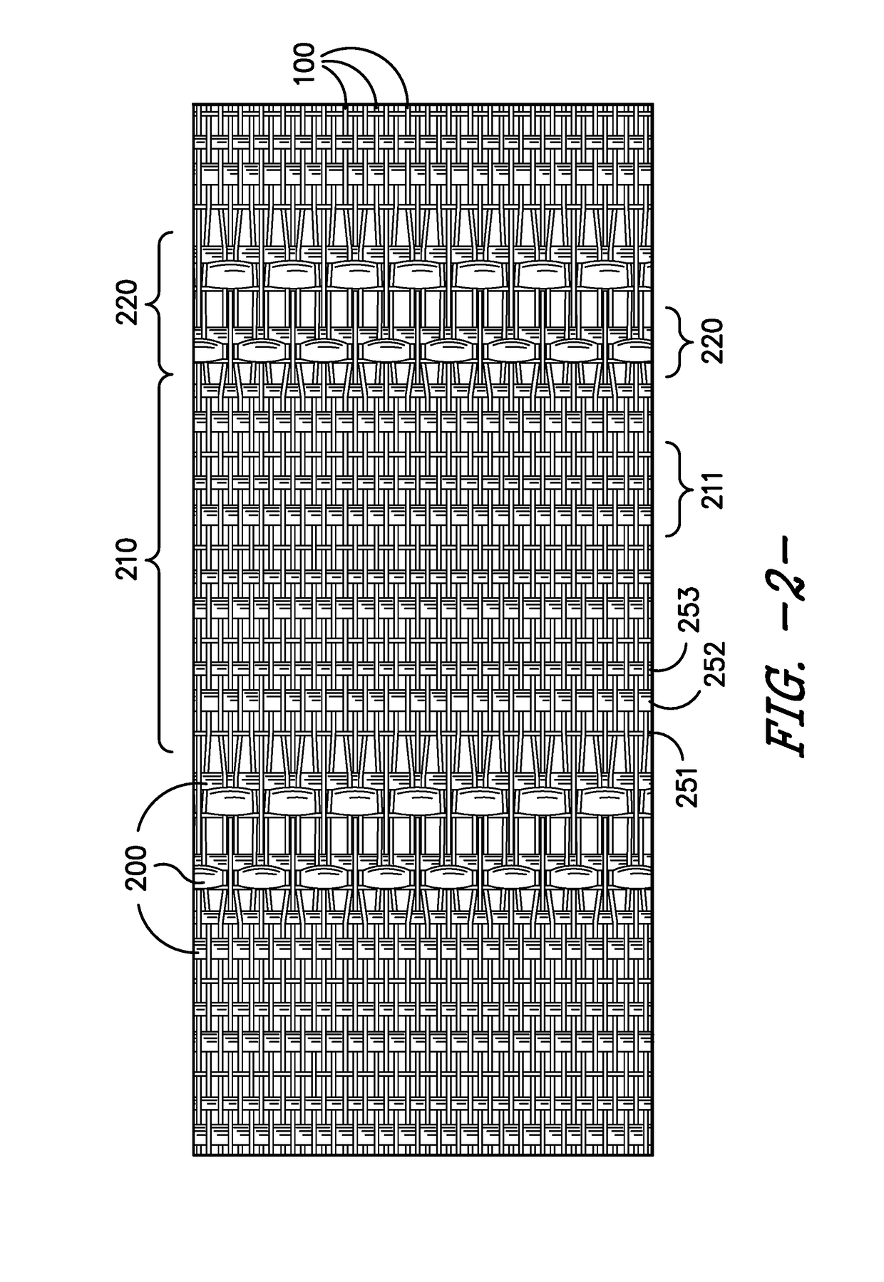
[0067]A textile fabric (shown in FIG. 2) was constructed the same as Example 1, except that the first weave contains 4 full sets of the plain weave zone repeat.

example 3

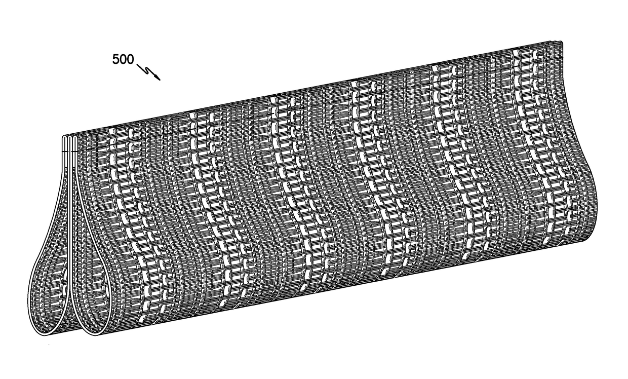
[0068]A textile fabric having the following characteristics was woven on a Dornier HTVS 4 / S 220 cm machine. The multifilament polyester filling yarns were double. The fabric was finished, slit and sewn into a tear-drop configured innerduct structure, as shown in FIG. 4, with two compartments, corresponding to Milliken & Company MaxCell® style 4418-2.

[0069]Warp: 48 ends per inch of 520 denier PET monofilament yarn;

[0070]Filling: 18 picks per inch, in a six pick repeat (1) 520 denier nylon 6 monofilament yarn; (2) double insertion of 681 denier textured PET multifilament yarn (two-ply 300 denier / 68 filaments; (3) double insertion of 681 denier textured PET multifilament yarn (two-ply 300 denier / 68 filaments; (4) 350 denier nylon 6 monofilament yarn; (5) double insertion of 681 denier textured PET multifilament yarn (two-ply 300 denier / 68 filaments; and (6) double insertion of 681 denier textured PET multifilament yarn (two-ply 300 denier / 68 filaments. The weight of the fabric was 5.8 ...


PUM

PropertyMeasurementUnit
Widthaaaaaaaaaa

Abstract

A woven fabric containing an alternating pattern containing first weave zones and partial float weave zones. The woven fabric contains a plurality warp yarns arranged into groupings of warp yarns. In each first weave zone, the picks of weft yarns contain a repeating first weft pattern. In each partial float zone, the picks of weft yarns within the partial float weave zone contain a repeating second weft pattern of at least one monofilament yarn and at least one multiple-inserted multifilament yarn. Within the partial float zone, only a portion of the warp yarns within at least a portion of the warp groupings float over 3 weft yarns including floating over at least one multiple-inserted multifilament weft yarn in at least a portion of weft pattern repeats. An innerduct structure containing the woven fabric is also described.

Description

TECHNICAL FIELD OF THE INVENTION[0001]The present invention is directed towards woven fabrics having partial float weave zones, more particularly for innerduct structures using woven fabrics having partial float weave zones.BACKGROUND[0002]Cable, such as fiber optic communication cable, is often provided underground in great lengths, and may even extend for many miles. It is known in the art to bury the cable in the ground so that the area above-ground is not cluttered with the cable and its respective support apparatus. Furthermore, by positioning the cable underground, it is more protected from the weather and other potentially damaging circumstances.[0003]It is also known in the cable art to position the cable within a conduit in order to more fully protect the cable during in-ground installations. The conduit, which is often formed from lengths of polyvinyl chloride tubing or the like, is laid in the ground, after which a rope is placed in the conduit either by blowing or roddin...

Claims


Application Information

Patent Timeline
IPC IPC(8): D03D1/04G02B6/50G02B6/44D03D13/00H02G9/06
CPCD03D1/04D03D13/00G02B6/50G02B6/4459H02G9/06D03D13/004D03D21/00D03D15/513D03D1/0043D03D1/0088
Inventor BEDINGFIELD, STEVEN L.DURHAM, CHRISTOPHER G.
Owner MILLIKEN & CO
Why Eureka
Try Eureka