Mouse pad structure

a mouse pad and structure technology, applied in the field of mouse pads, can solve the problems of user discomfort after rubbing and touching the sharp edges for a long time, and affect the operation and appearance, and achieve the effects of improving the movement accuracy of the optical mouse device, improving the practicability, and improving the texture of the pattern layer

Inactive Publication Date: 2017-05-25
HADES GAMING CORP
View PDF6 Cites 0 Cited by
  • Summary
  • Abstract
  • Description
  • Claims
  • Application Information

AI Technical Summary

Benefits of technology

[0009]The present invention is to provide a mouse pad structure, in which a pattern layer is disposed between a pad body and a plastic film, and the texture of the pattern layer can be altered according to actual needs, so that the practicability can be increased.
[0010]The present invention is to provide a mouse pad structure, in which a plurality of textures are formed on a plastic film, so when an optical mouse device is used thereon, the movement accuracy of an optical mouse device can be enhanced, so that the practicability can be increased.
[0011]In comparison with related art, the present invention has advantageous features as follows. According to the mouse pad structure provided by the present invention, the plastic film is combined with the pad body, and the plastic film is flatly adhered on the top surface and the outer periphery of the pad body for covering the sharp edges formed on the pad body; thus, when a user's hand closely contacts the sharp edges, uncomfortable operation feelings can be avoided after rubbing against the sharp edges for a long period of time.

Problems solved by technology

However, after the fabric on the surface layer of the mouse pad has been used for a long period of time, the fabric may be slightly peeled off or separated from the pad body, thus the operation and the appearance may be affected.
When a user's hand closely contacts the surface layer of the mouse pad and moves thereon, the user may feel uncomfortable after contacting and rubbing against the sharp edges for a long time.

Method used


Image

  • Mouse pad structure
  • Mouse pad structure
  • Mouse pad structure

Examples


Embodiment Construction

[0018]Preferred embodiments of the present invention will be described with reference to the drawings.

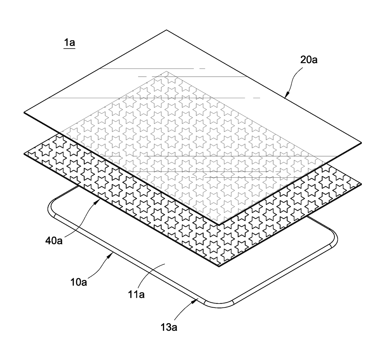
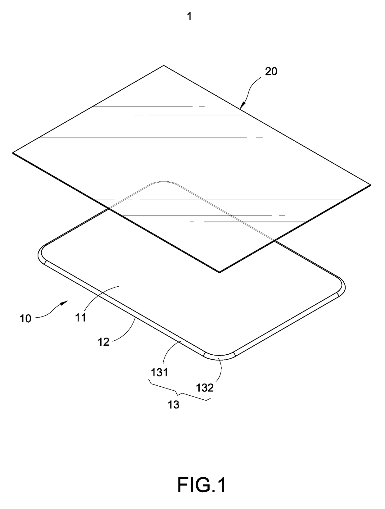
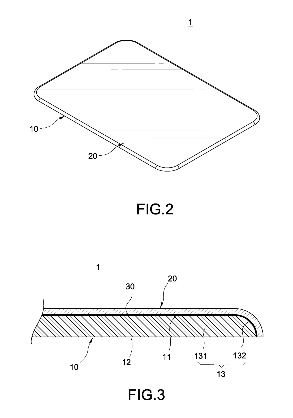
[0019]Please refer from FIG. 1 to FIG. 3, wherein FIG. 1 is a perspective exploded view showing a mouse pad structure according to one embodiment of the present invention; FIG. 2 is a perspective view showing the assembly of the mouse pad structure according to one embodiment of the present invention; and FIG. 3 is a partial cross sectional view showing the assembly of the mouse pad structure according to one embodiment of the present invention. The present invention provides a mouse pad structure 1, which includes a pad body 10 and a plastic film 20. The plastic film 20 is combined with the pad body 10, so that the mouse pad structure 1 is formed and capable of being used with a mouse device.

[0020]The pad body 10 is formed as a flat plate member and made of a material such as silicon, rubber and sponge, and the above-mentioned material can be selectively adopted according to actual...


PUM


Abstract

A mouse pad structure includes a pad body and a plastic film. The pad body is formed as a flat plate member and formed with a top surface, a bottom surface opposite to the top surface, and an outer periphery defined between the top surface and the bottom surface. The plastic film is flatly adhered and covered on the top surface and the outer periphery of the pad body. Accordingly, the mouse pad structure is able to provide comfortable operation feelings and increase the movement accuracy defined when a mouse device is operated thereon.

Description

BACKGROUND OF THE INVENTION[0001]Field of the Invention[0002]The present invention relates to a computer accessory for inputting data, especially to a mouse pad structure.[0003]Description of Related Art[0004]An optical mouse device is commonly used as a computer accessory, the optical mouse device emits LED lights to a mouse pad, and the lights are reflected and then refracted through a lens to a sensor, so the movement and moving direction of the mouse device can be detected. For an optical mouse device, a mouse pad is only for assisting the mouse device to move, the mouse pad is also served as an important reflection interface assisting an optical sensor to receive data. Thus, a proper mouse pad plays an important role regarding to the operation convenience.[0005]In addition, a surface layer of the conventional mouse pad adopts a fabric providing softer touching feelings, so a better operation feeling when operating the mouse device is provided. However, after the fabric on the s...

Claims


Application Information

Patent Timeline
Patent Type & Authority Applications(United States)
IPC IPC(8): G06F3/039
CPCG06F3/0395
Inventor CHOU, HUNG-JEN
Owner HADES GAMING CORP
Why Eureka
Try Eureka