Liquid cooling station

a cooling station and liquid technology, applied in the direction of electrical apparatus construction details, light and heating apparatus, heat exchanger casings, etc., can solve the problems of need for sealing between the different components and so as to reduce the risk of cooling liquid leakage and the number of connections

Active Publication Date: 2017-05-25
ADWATEC
View PDF1 Cites 1 Cited by
  • Summary
  • Abstract
  • Description
  • Claims
  • Application Information

AI Technical Summary

Benefits of technology

[0008]The connection block provides a compact element for connecting the parts of the cooling station, like the pumps, the motors and the heat exchanger together, whereby all the pipes or hoses used earlier to connect those parts together in the cooling station may be left out. This also provides that a number of connections are reduced too. As a consequence of that risks for cooling liquid leakages are reduced.

Problems solved by technology

This, in turn, increases a need for sealing between the different components as well as a risk for leakages of the cooling liquid.

Method used


Image

  • Liquid cooling station
  • Liquid cooling station
  • Liquid cooling station

Examples


Embodiment Construction

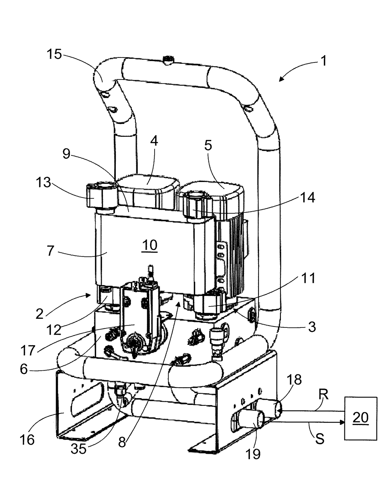
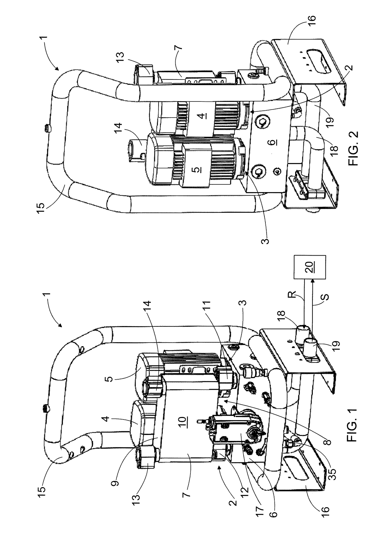
[0018]FIG. 1 is a schematic oblique front view of a liquid cooling station 1 and FIG. 2 is a schematic oblique back view of the liquid cooling station 1 of FIG. 1. Later the liquid cooling station 1 may also be called the cooling station 1. The cooling station 1 of FIGS. 1 and 2 comprises a first pump 2 and a first motor 4 connected to the first pump 2 for operating the first pump 2 to circulate a cooling liquid between the cooling station 1 and an object 20 to be cooled. In the object 20 to be cooled an excessive heat in the object 20 is transferred to a cooling liquid flow and by the cooling liquid flow out of the object 20 to be cooled.

[0019]The cooling station 1 comprises also a second pump 3 and a second motor 5 connected to the second pump 3 for operating the second pump 3 to also circulate the cooling liquid between the cooling station 1 and the object 20 to be cooled. In the embodiment of FIGS. 1 and 2 the first motor 4 and the second motor 5 are electric motors, but, depend...


PUM


Abstract

Liquid cooling station comprises at least one pump and at least one motor connected to the pump for operating the pump to circulate cooling liquid between the cooling station and an object to be cooled, a first cooling liquid outlet port for supplying the cooling liquid towards the object to be cooled and a first cooling liquid inlet port for receiving the cooling liquid from the object to be cooled. The liquid cooling station further comprises at least one connection block, which comprises at least one first cavity for receiving an operating part of the pump, at least one second cavity for an additional operational part, the first cooling liquid inlet and outlet ports and an internal channel system connecting the first cavity to the first cooling liquid inlet and outlet ports.

Description

FIELD OF THE INVENTION[0001]The invention relates to a liquid cooling station.BACKGROUND OF THE INVENTION[0002]A cooling arrangement or system and a liquid cooling station therein are used to transfer heat away from an object to be cooled, like a power electronic device.[0003]The liquid cooling station comprises a pump and a motor connected thereto for operating the pump to circulate cooling liquid between the cooling station and an object to be cooled. The cooling station also comprises a heat exchanger to transfer the heat away from the cooling liquid flow either to ambient air of the installation site of the liquid cooling station or to separate technical liquid flow intended to receive the heat from the cooling liquid flow. The cooling station receives the cooling liquid flow from the object to be cooled through an inlet channel and supplies the cooling liquid flow towards the object to be cooled through an outlet channel. Furthermore the liquid cooling station may comprise a de...

Claims


Application Information

Patent Timeline
Patent Type & Authority Applications(United States)
IPC IPC(8): H05K7/20F28F9/26F04D13/06F28F23/00
CPCH05K7/20272F28F23/00F28F2265/14H05K7/20263F04D13/06F28F9/262
Inventor VERRONEN, ARTOSIITONEN, MIKATERAVA, JORMA
Owner ADWATEC
Why Eureka
Try Eureka