

Ablation catheter and ablation apparatus
a catheter and ablation technology, applied in the field of catheters and ablation devices, can solve the problems of piercing of the heart wall, critical damage, and special delicate operation, and achieve the effects of avoiding re-treatment, eliminating eddy currents, and precise ablation catheters
- Summary
- Abstract
- Description
- Claims
- Application Information
AI Technical Summary
Benefits of technology
Problems solved by technology
Method used
Image

Examples
Embodiment Construction
[0088]Whereas the invention can undergo various modifications and alternative constructions, some relative illustrative embodiments are shown in the drawings and are described hereunder in detail.
[0089]It should be understood, however, that there is no intention of limiting the invention to the specific embodiment illustrated but, on the contrary, the invention intends to cover all the modifications, alternative constructions, and equivalents that fall within the scope of the invention as defined in the claims.
[0090]The use of “for example”, “etc.”, “or” indicates non-exclusive alternatives, without limitation, unless otherwise specified. The use of “comprises” means “comprises, but not limited to” unless otherwise specified.
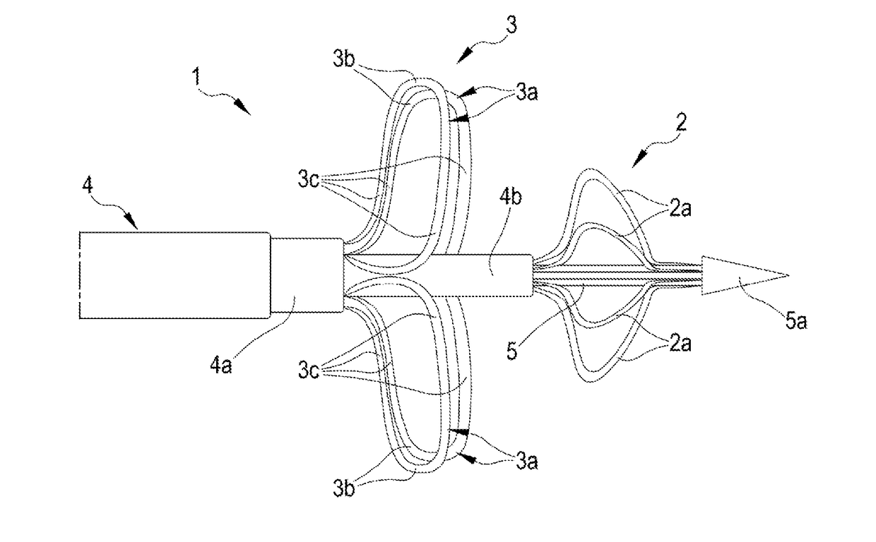
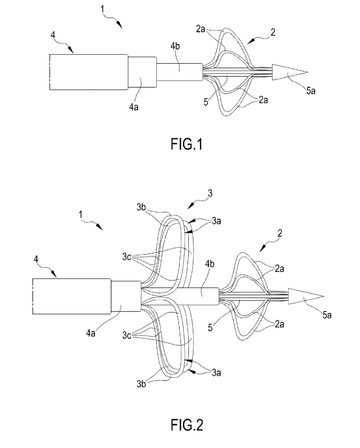
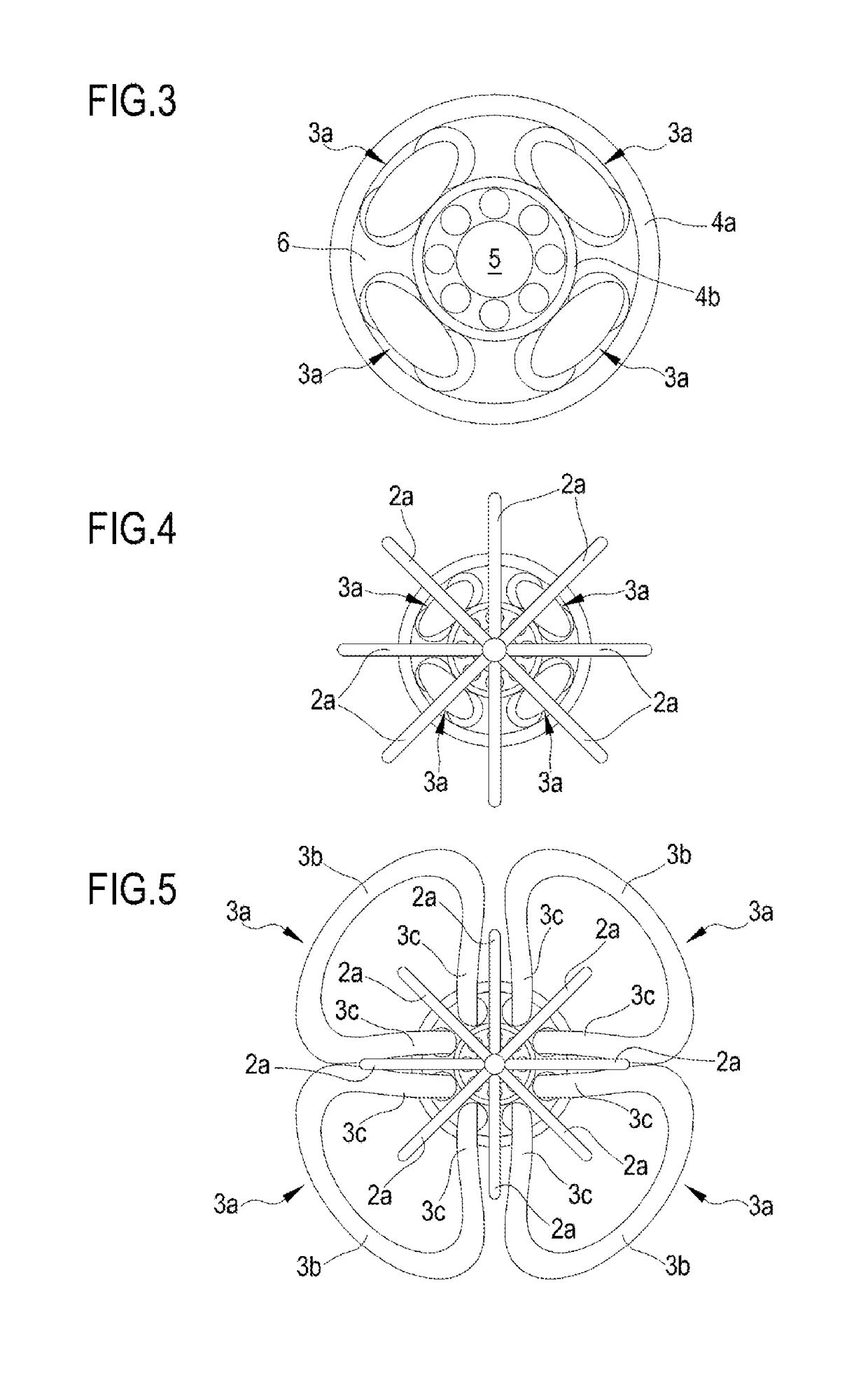
[0091]With reference to the enclosed figures, these show an illustrative but non-limiting embodiment of the catheter of the invention, indicated as a whole with reference 1.
[0092]The catheter 1 comprises a positioning head 2 and an ablation head 3, which will be...
PUM
 Abstract
Description
Claims
Application Information