Bolt cutter

a bolt cutter and adjustment technology, applied in the field of cutters, can solve problems such as size constraints

Active Publication Date: 2017-06-15
MILWAUKEE ELECTRIC TOOL CORP
View PDF13 Cites 6 Cited by
  • Summary
  • Abstract
  • Description
  • Claims
  • Application Information

AI Technical Summary

Problems solved by technology

These cutters utilize mechanical advantage to increase the user's ability to apply a

Method used


Image

  • Bolt cutter
  • Bolt cutter
  • Bolt cutter

Examples


Embodiment Construction

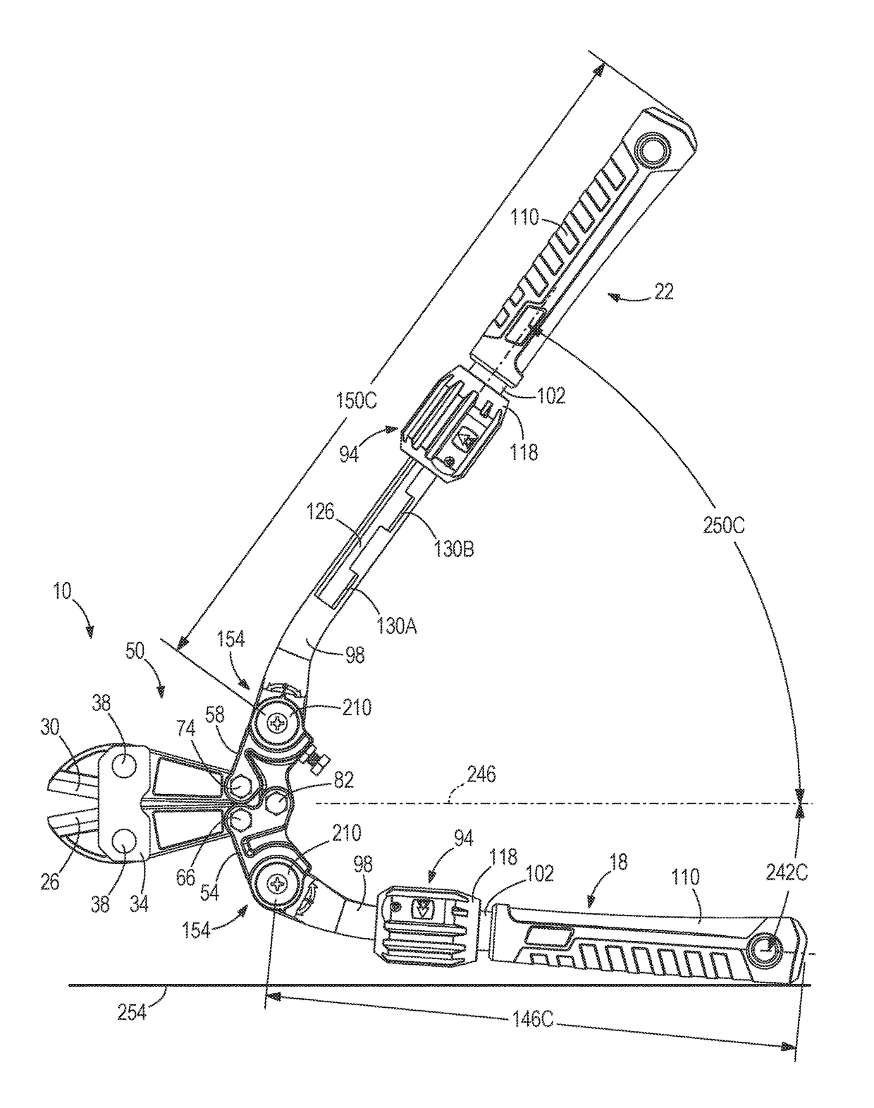
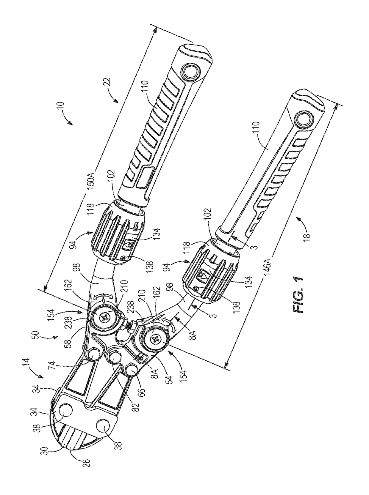
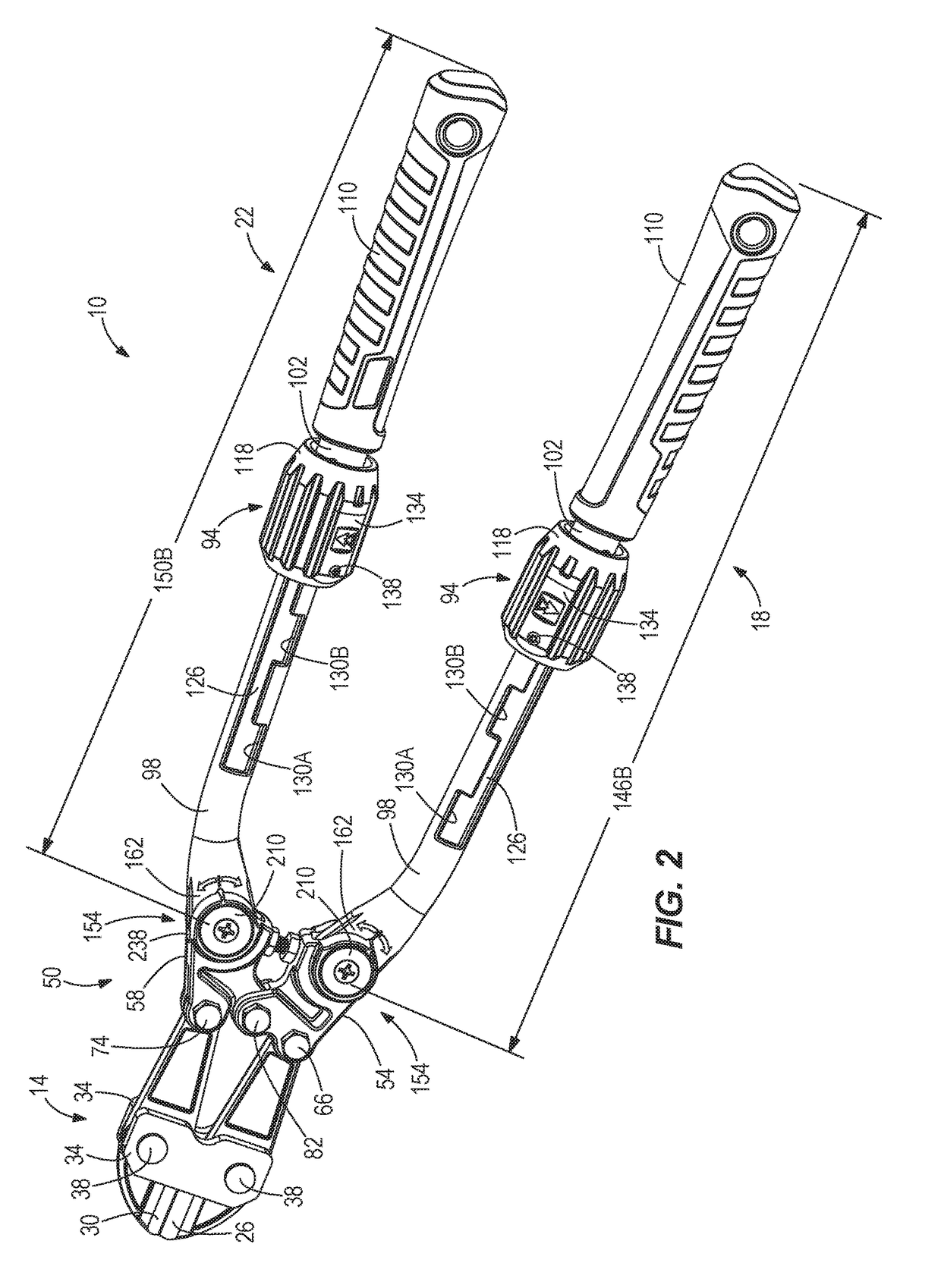
[0022]With reference to FIGS. 1-2, a bolt cutter 10 is illustrated including a cutting head 14, a first adjustable handle 18, and a second adjustable handle 22. The cutting head 14 includes a first cutting blade 26 and a second cutting blade 30 coupled together by plates 34 and corresponding fasteners 38. The first cutting blade 26 and the second cutting blade 30 are pivotable about a pin 42 (FIG. 6) that is sandwiched between the plates 34. The pin 42 allows the first and second cutting blades 26, 30 to move with respect to each other about an axis 46 (FIG. 6) defined by the pin 42. Specifically, the first and second cutting blades 26, 30 are movable between an open position (i.e., with the cutting portions of the blades 26, 30 spaced apart; FIG. 9) and a closed position (i.e., with the cutting portions of the blades 26, 30 together; FIG. 1). As the first and second blades 26, 30 are moved from the open position to the closed position; an object (e.g., chains, padlocks, bolts, etc....


PUM


Abstract

A cutter including a cutting head and an adjustable handle pivotally coupled to the cutting head. The adjustable handle includes a first adjustment assembly to change a length the adjustable handle extends from the cutting head. The adjustable handle also includes a second adjustment assembly to change the position of the adjustable handle with respect to the cutting head.

Description

CROSS-REFERENCE TO RELATED APPLICATIONS[0001]This application claims priority to co-pending U.S. Provisional Patent Application No. 62 / 265,536, filed on Dec. 10, 2015, the entire contents of which are incorporated herein by reference.FIELD OF THE INVENTION[0002]The present invention relates to a cutter, and more specifically to an adjustable bolt cutters.BACKGROUND OF THE INVENTION[0003]There are various hand tools known in the art for cutting a workpiece (e.g., a bolt). These cutters utilize mechanical advantage to increase the user's ability to apply a cutting force on the workpiece, but often these designs are met with size constraints.SUMMARY OF THE INVENTION[0004]The invention provides, in one aspect, a cutter including a cutting head and an adjustable handle pivotally coupled to the cutting head. The adjustable handle includes a first adjustment mechanism to change a length the adjustable handle extends from the cutting head. The adjustable handle further includes a second adj...

Claims


Application Information

Patent Timeline
IPC IPC(8): B26B17/02B25G1/06B25G1/04
CPCB26B17/02B25G1/06B25G1/04B25G1/043B25G1/066
Inventor FEUERSTEIN, JACOBHOPPE, CHRISTOPHER S.GRAYKOWSKI, ANTHONYLI, CHENG ZHANG
Owner MILWAUKEE ELECTRIC TOOL CORP
Why Eureka
Try Eureka