Held gear wire clipper

A technology of wire cutters and gears, which is applied in the field of pliers to achieve the effects of accurate action, light structure and convenient use.

Inactive Publication Date: 2012-05-02
李炜
View PDF0 Cites 3 Cited by
  • Summary
  • Abstract
  • Description
  • Claims
  • Application Information

AI Technical Summary

Problems solved by technology

[0004] According to the search, there is no patent ap

Method used


Image

  • Held gear wire clipper
  • Held gear wire clipper
  • Held gear wire clipper

Examples


Embodiment Construction

[0013] The present invention will be further described by utilizing the accompanying drawings.

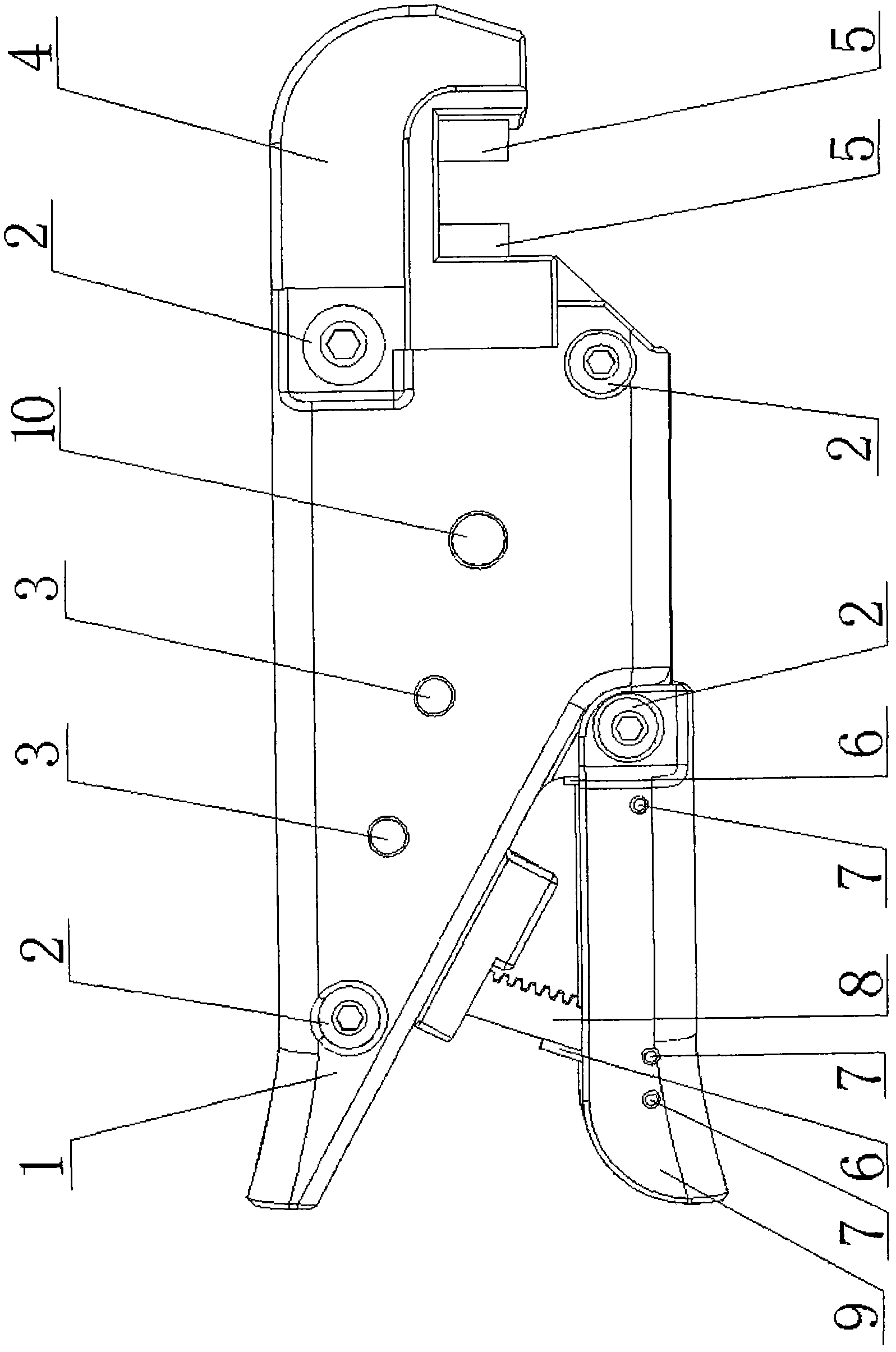
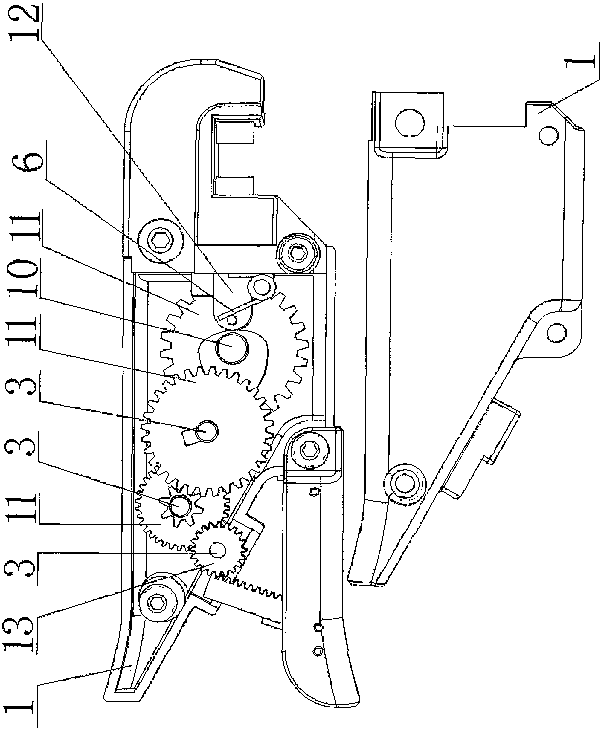
[0014] When the present invention is installed, the tool rest 4, the cutter head 5, the torsion spring 6 and the push rod 12 are installed first, and then the flywheel 13, the pinion shaft 3, the gear 11 and the camshaft 10 are respectively installed in the handle box 1 on one side, Close the handle box 1 on the other side, and then use the bolt 2 to connect and fix them. Gear bar 8 is installed in movable handle 9 with pin 7, torsion spring 6, puts one end of tooth bar 8 in the handle box and puts it away, and is connected on the handle box 1 with torsion spring 6 and bolt 2 again.

[0015] During work, hold the movable handle 9 to make the two cutter heads 5 reach a suitable distance, put the steel wire rod between the two cutter heads 5, and constantly hold the movable handle 9 so that the rack 8 drives the flywheel 13, the pinion 3. The gear set formed by the gear 11 rotates, ...


PUM


Abstract

The invention discloses a held gear wire clipper, and relates to plier tools, in particular to a tool for shearing reinforcing steel bars, which belongs to wire clippers. The technical schemes of existing wire clippers are various, and the existing wire clippers capable of shearing the reinforcing steel bars mostly adopt a hydraulic principle, a lever principle and an incomplete gear type and are all held with double hands. The wire clipper adopting the hydraulic principle is precise in manufacture, high in cost and labor-consuming in maintenance. The wire clipper adopting the lever principle is large in size, heavy in weight and inconvenient to carry while a small wire clipper cannot shear off thicker reinforcing steel bars. The incomplete gear type wire clipper of a larger size is mainly used for shearing soft wires such as cables. The scheme of the held gear wire clipper includes that a rack, a flywheel, a multistage gear set and a cam shaft are combined to shear armature wires, and the held gear wire clipper is simple in structure, reliable in operation, low in cost, small in size and light in weight, is capable of partially replacing a traditional wire clipper, and can be operated with a single hand.

Description

technical field [0001] The invention relates to a pliers tool, especially a break pin tool for cutting steel bars. Background technique [0002] The technical scheme of existing bolt cutter has multiple, and what can cut steel bar mostly is with hydraulic principle, lever principle and incomplete gear formula three kinds of modes and is both hands holding. Hydraulic bolt cutters are manufactured precisely, with high cost and laborious maintenance. The bolt cutters based on the leverage principle are large in size and heavy in weight, making it inconvenient to carry, and the small ones cut continuously thicker steel bars. Incomplete gear type, the volume is too large, and it is mostly used to cut soft wires such as cables. [0003] The present invention adopts the combination of rack, flywheel, multi-stage gear set and camshaft to cut steel bar wire, which has simple structure, reliable operation, low cost, small size and light weight, can partially replace traditional bolt...

Claims


Application Information

Patent Timeline
IPC IPC(8): B21F11/00
Inventor 李炜
Owner 李炜
Why Eureka
Try Eureka