Apparatus and method for optimizing ultrasonic signal

an ultrasonic signal and optimizing method technology, applied in the field of optimizing an ultrasonic signal, can solve the problems of ultrasonic sensor beam, malfunction, and different wavelengths, and achieve the effect of minimizing residual oscillations and improving the minimum sensing distance performan

Active Publication Date: 2017-06-15
HYUNDAI MOBIS CO LTD
View PDF16 Cites 8 Cited by
  • Summary
  • Abstract
  • Description
  • Claims
  • Application Information

AI Technical Summary

Benefits of technology

[0010]Aspects of the inventive concept provide an apparatus for optimizing an ultrasonic signal, the apparatus capable of improving minimum sensing distance performance by changing a set frequency of a signal transmitted from an ultrasonic sensor used in a vehicle. Specifically, residual oscillations of a transmitted ultrasonic signal are measured, and a compensation pulse which can minimize the residual oscillations is generated by comparing residual oscillations in a current period with residual oscillations in a previous period.

Problems solved by technology

Hence, malfunctions can arise depending on the location of a vehicle or the surrounding environment.
In addition, malfunctions may arise due to conditions in which an ultrasonic sensor beam is not reflected (e.g., a case where an ultrasonic wave is reflected by the windshield of a vehicle, a case where an upper surface of a vehicle is rounded too much, or a case where no reflected wave is received because an ultrasonic wave is reflected by a front or rear rounded part of a small vehicle due to the small size of the vehicle).
For example, in the case of a truck, an information display malfunction may arise depending on the degree to which goods are piled in a cargo box of the truck.
In the case of a tall vehicle, a malfunction may arise due to the non-sensing distance of the ultrasonic sensor.
In addition, residual oscillation of the ultrasonic sensor may increase according to temperature and environment.
However, since a compensation pulse set in a particular temperature condition is used to reduce the residual oscillation, it is not possible to minimize the residual oscillation in various environmental conditions.

Method used


Image

  • Apparatus and method for optimizing ultrasonic signal
  • Apparatus and method for optimizing ultrasonic signal
  • Apparatus and method for optimizing ultrasonic signal

Examples


Embodiment Construction

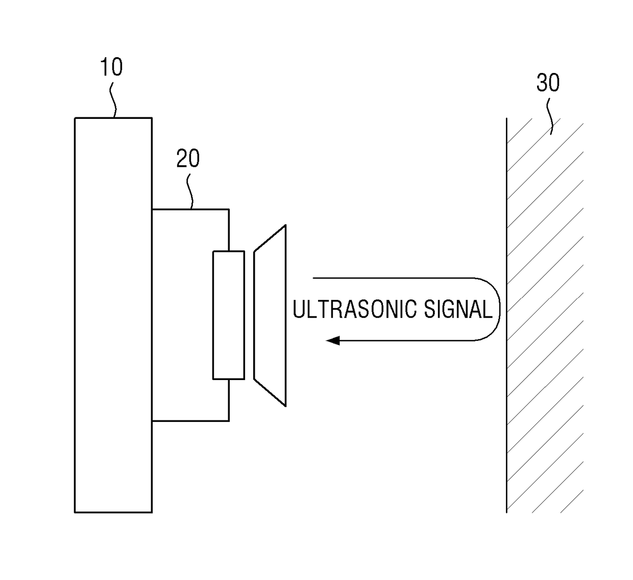
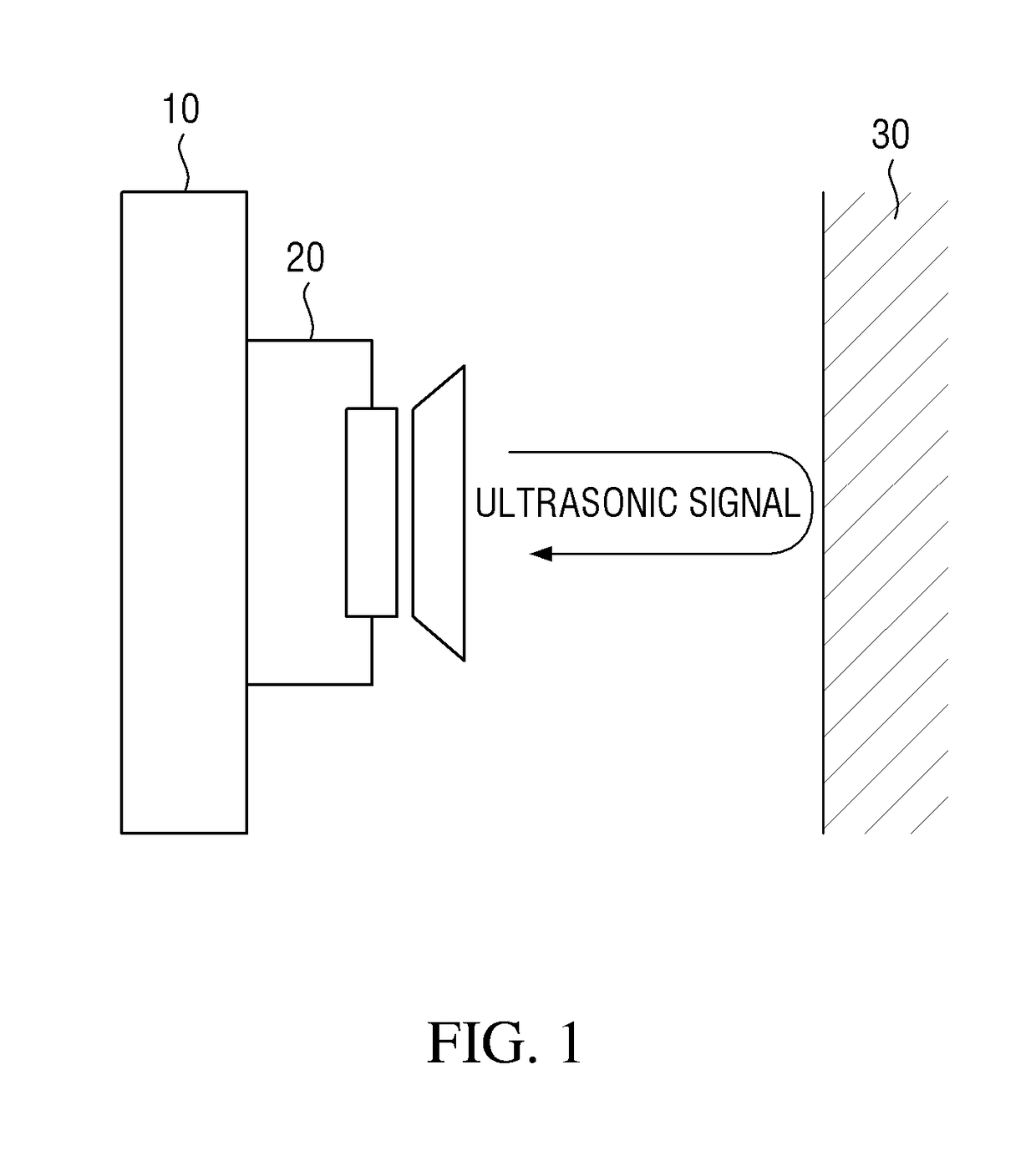
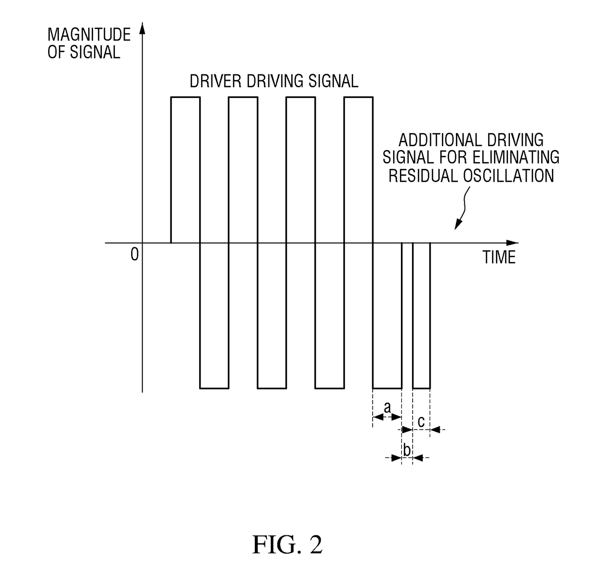
[0021]An apparatus and method for optimizing an ultrasonic signal according to the inventive concept are used in a front and rear parking assistance system in order to make up for a reduction in the minimum sensing distance performance of an ultrasonic sensor due to an increase in the residual oscillation of the ultrasonic sensor according to temperature and environment by optimizing the residual oscillation of the ultrasonic sensor. After an ultrasonic sensor transmits an ultrasonic signal, residual oscillation of the ultrasonic sensor is measured, and then a frequency pulse optimally corrected within a parameter range is calculated to optimize the residual oscillation of the ultrasonic sensor.

[0022]Specifically, a transducer of an ultrasonic sensor has an operating frequency and characteristics that vary according to temperature. However, a conventional front and rear ultrasonic distance measurement apparatus for vehicles uses, in all temperature ranges, a correction frequency set...


PUM


Abstract

Apparatus and method for optimizing an ultrasonic signal are provided, one of apparatus comprises, an ultrasonic signal sensing unit which transmits and receives an ultrasonic signal, a residual oscillation measurement unit which measures a first ringing time of the ultrasonic signal transmitted from the ultrasonic signal sensing unit, a comparison and calculation unit which compares the first ringing time with a pre-stored second ringing time and calculates a correction frequency based on the comparison result, an electrical damping pulse generation unit which generates an electrical damping pulse having the correction frequency and a control unit which controls the electrical damping pulse to be applied to the ultrasonic signal sensing unit.

Description

[0001]This application claims the benefit of Korean Patent Application No. 10-2015-0179093, filed on Dec. 15, 2015, in the Korean Intellectual Property Office, the disclosure of which is incorporated herein by reference in its entirety.BACKGROUND[0002]1. Field[0003]The present inventive concept relates to an apparatus and method for optimizing an ultrasonic signal, and more particularly, to an apparatus and method for optimizing an ultrasonic signal, the apparatus and method being employed to improve the minimum sensing distance performance of an ultrasonic sensor used in a front and rear parking assistance system by correcting an ultrasonic sensor pulse to minimize the residual oscillation of the ultrasonic sensor.[0004]2. Description of the Related Art[0005]Generally, a parking assistance system using an ultrasonic sensor receives a reflected wave of an ultrasonic wave transmitted from an ultrasonic sensor installed on each of the front and back of a vehicle. The parking assistanc...

Claims


Application Information

Patent Timeline
Patent Type & Authority Applications(United States)
IPC IPC(8): G01S7/527G01S15/10G01S15/93G01S15/931
CPCG01S7/5276G01S2015/932G01S15/10G01S15/931G01S7/52004G01S7/52006G01S7/524
Inventor KIM, HYUN
Owner HYUNDAI MOBIS CO LTD
Why Eureka
Try Eureka