System and Method for Controlling Autonomous Vehicles

a technology for autonomous vehicles and control systems, applied in process and machine control, instruments, navigation instruments, etc., can solve problems such as complicated paths that reach, and achieve the effect of optimizing the movement of the vehicl

Active Publication Date: 2017-06-15
MITSUBISHI ELECTRIC RES LAB INC
View PDF1 Cites 85 Cited by
  • Summary
  • Abstract
  • Description
  • Claims
  • Application Information

AI Technical Summary

Benefits of technology

[0007]Some embodiments of an invention are based on recognition that an optimal path of a vehicle from the initial location to a target location does not necessarily correspond to the optimal motion of the vehicle. The underactuated nature of the vehicle can lead to more optimal state transitions between states of the vehicle that are different from the transitions along the shortest possible path leading to the target location. The states of the vehicle include dynamics of the vehicle, such as locations, velocities and headings of the vehicles. Therefore, more optimal state transitions lead to more optimal motion of the vehicle.

Problems solved by technology

For example, the heading of the vehicle at the second location can result in a complicated path that reaches the location.

Method used


Image

  • System and Method for Controlling Autonomous Vehicles
  • System and Method for Controlling Autonomous Vehicles
  • System and Method for Controlling Autonomous Vehicles

Examples


Embodiment Construction

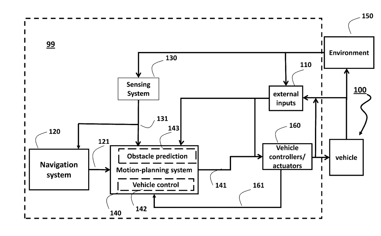
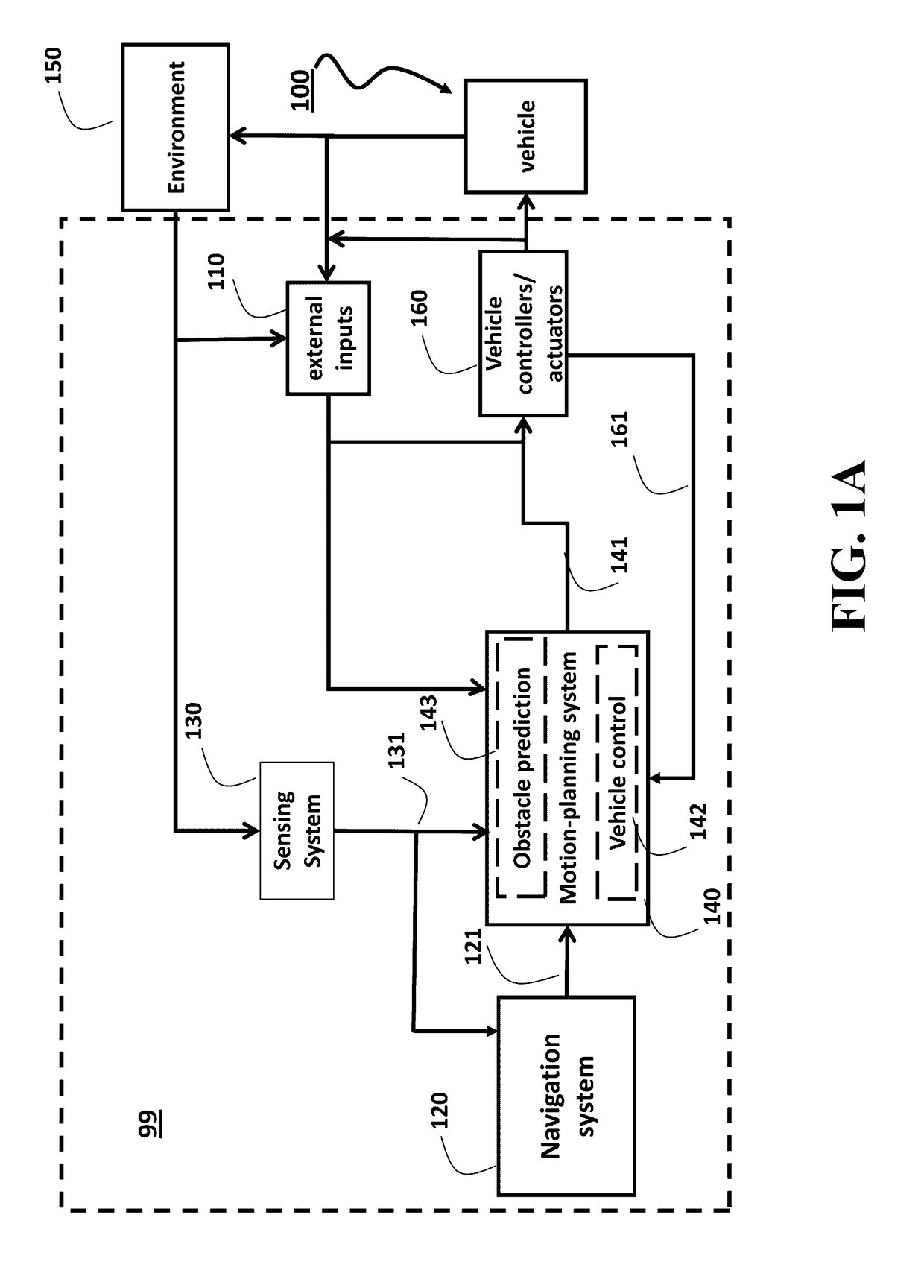
[0033]FIG. 1 shows a block diagram of a control system 99 for controlling a vehicle 100 according to some embodiments of the intervention. The vehicle can be any type of moving vehicle equipped with an autonomous system. The vehicle can also receive external inputs 110 overriding the commands of the control system 99. In such a case the vehicle is a semi-autonomous vehicle. As one example, the vehicle 100 can be a four-wheel passenger car. Another example of a possible vehicle is a differential-drive mobile robot, and / or an unmanned aerial vehicle.

[0034]The control system 99 includes a navigation system 120 for determining an initial location and a target location of the vehicle. For example, the navigation system 120 can include GPS and / or an inertial measurement unit (IMU). For example, the IMU can comprise 3-axis accelerometer(s), 3-axis gyroscope(s), and / or magnetometer(s). The IMU can provide velocity, orientation, and / or other position related information to other components o...


PUM


Abstract

A method determines iteratively a motion of the vehicle from an initial location and a target location. An iteration of the method determines a location between the initial location and the target location that satisfies spatial constraints on locations of the vehicle and determines state transitions of the vehicle moved to the location from a set of neighboring locations determined during previous iterations. The method selects a neighboring location resulting in an optimal state transition of the vehicle and updates a graph of state transitions of the vehicle determined during previous iterations with the optimal state transition. The motion of the vehicle is determined a sequence of state transitions connecting the initial location with the target location and the vehicle is controlled according to the determined motion.

Description

FIELD OF THE INVENTION[0001]The present invention relates generally to controlling vehicles, and more particularly to controlling a vehicle, such as an autonomous or a semi-autonomous vehicle.BACKGROUND OF THE INVENTION[0002]Some of the control systems used in autonomous vehicles aims to move the vehicles through the surroundings, by predicting safe motions for the vehicle avoiding obstacles. The surroundings, such as road edges, pedestrians, and other vehicles, are sensed by the sensors of the vehicle and / or at least partially known by a priori given information. However, the sensor information is noisy and uncertain and the control of the vehicle should account for such an uncertainty. Moreover, it is also can be important to optimize the operation of the vehicle associated with the predicted motion.[0003]For example, if an autonomous vehicle travels along a road segment, the control system of the autonomous vehicle can generate a motion that minimizes one or combinations of devia...

Claims


Application Information

Patent Timeline
Patent Type & Authority Applications(United States)
IPC IPC(8): G05D1/00G05D1/02G01C21/34G01C21/26
CPCG05D1/0088G01C21/3453G05D1/0214G01C21/26G01C21/20G05D1/0274G05D1/0217B60W30/00B60W60/0011B60W60/00276
Inventor BERNTORP, KARLARSLAN, OKTAY
Owner MITSUBISHI ELECTRIC RES LAB INC
Why Eureka
Try Eureka