Multi-motion lifting and transferring apparatus and method

a technology of lifting and transferring apparatus and method, which is applied in the direction of roofs, transportation items, refuse collection, etc., can solve the problems of limiting the potential mobility of a disabled individual, difficult to lift and transfer such persons to and from their wheelchairs, and difficulty in transferring disabled persons from one location. , to achieve the effect of preventing excessive movement and/or rotation

Active Publication Date: 2011-01-04
EGAN THOMAS F
View PDF87 Cites 19 Cited by
  • Summary
  • Abstract
  • Description
  • Claims
  • Application Information

AI Technical Summary

Benefits of technology

[0007]A multi-motion lifting and transferring apparatus and method are disclosed. The multi-motion lifting and transferring apparatus and method may be realized in primarily two versions, the first being referred to as the single linkage arm version, and the second being referred to as the dual linkage arm version. In one particular exemplary embodiment, a multi-motion lifting and transferring apparatus in accordance with the single linkage arm version may be realized as having a first pivot point for rotating an intermediary support member about a first substantially vertical axis, a second pivot point for rotating an electrically or hydraulically powered up / down extension arm about a second substantially vertical axis, and a seat support member for supporting a seat for accommodating at least one person. In another particular exemplary embodiment, a multi-motion lifting and transferring apparatus in accordance with the multiple linkage arm version may be realized as having a first pivot point for rotating a first intermediary support member about a first substantially vertical axis, a second pivot point for rotating a second intermediary support member about a second substantially vertical axis, a third pivot point for rotating an electrically or hydraulically powered up / down extension arm about a third substantially vertical axis, and a seat support member for supporting a seat for accommodating at least one person. Additional flexibility in overcoming vehicle structural obstructions may be gained by adding additional pivot points.
[0009]In accordance with further aspects of these particular exemplary embodiments, the first intermediary support member pivots about the first substantially vertical axis, allowing for initial rearward motion (e.g., towards the rear of a vehicle) of the seat and seat support member to increase ergonomic ease and legroom, followed by a reverse rotation which moves the second pivot point closer to a door opening space. In the case of the single linkage arm version, the second pivot point, rotating about the second substantially vertical axis, then facilitates the rotation of the hydraulically or electrically powered up / down extension arm to position the attached seat support member and seat optimally within a door opening space. In the case of the multiple linkage arm version, the second pivot point, rotating about the second substantially vertical axis, then facilitates the rotation of the second intermediary support member, connected via the third pivot point rotating about the third substantially vertical axis to the hydraulically or electrically powered up / down extension arm to position the attached seat support member and seat optimally within a door opening space.
[0011]In accordance with still other aspects of these particular exemplary embodiments, the pivot points may be electrically actuated to rotate each support member. The electrically actuated rotators may comprise an electrical or optical rotation measurement device for aiding a controller to memorize optimal motions. The electrically actuated rotators may also or alternatively comprise, in associated control circuitry, a door sensor electrical or optical switch, for preventing operation of the apparatus when a vehicle door is closed. The electrically actuated rotators may also or alternatively comprise, in associated control circuitry, electrical current load sensors, for preventing rotation of the apparatus when a barrier such as a human body part or other obstacle is encountered. The electrically actuated rotators may also or alternatively comprise, in associated control circuitry, optical sensors or electrical switches, for preventing rotation of the apparatus when a barrier such as a human body part or other obstacle is encountered in key obstruction areas.
[0014]In accordance with yet still other aspects of these particular exemplary embodiments, one or more of the electrically actuated rotators and the hydraulically or electrically powered up / down extension arm may include limit switches for preventing excessive movement and / or rotation inward or outward or upwards or downward.

Problems solved by technology

Difficulties are often encountered when transferring disabled persons from one location to another.
Particularly in the case of wheelchair-bound persons, it is often quite difficult to lift and transfer such persons to and from their wheelchair from and to, for example, a motor vehicle.
However, the devices disclosed in both of these patents, as well as other known devices, have drawbacks in the areas of cost and complexity which could limit the potential mobility of a disabled individual.
The device disclosed in U.S. Pat. No. 6,223,364 is incompatible with the functional and installation requirements of certain combinations of vehicles and users, in particular when a vehicle has a relatively small door opening and structural obstructions in the exit path of the seat, when users require extra legroom and a rearward motion of the seat prior to turning and exit.
The Turny turning automotive seat product manufactured by Bruno Corporation in the United States overcomes certain legroom restrictions with a limited rearward motion prior to exiting, however does not overcome many vehicle structures and other obstructions in the seat is exiting the vehicle.
Similar drawbacks exist for other known lifting and transferring devices.

Method used


Image

  • Multi-motion lifting and transferring apparatus and method
  • Multi-motion lifting and transferring apparatus and method
  • Multi-motion lifting and transferring apparatus and method

Examples


Embodiment Construction

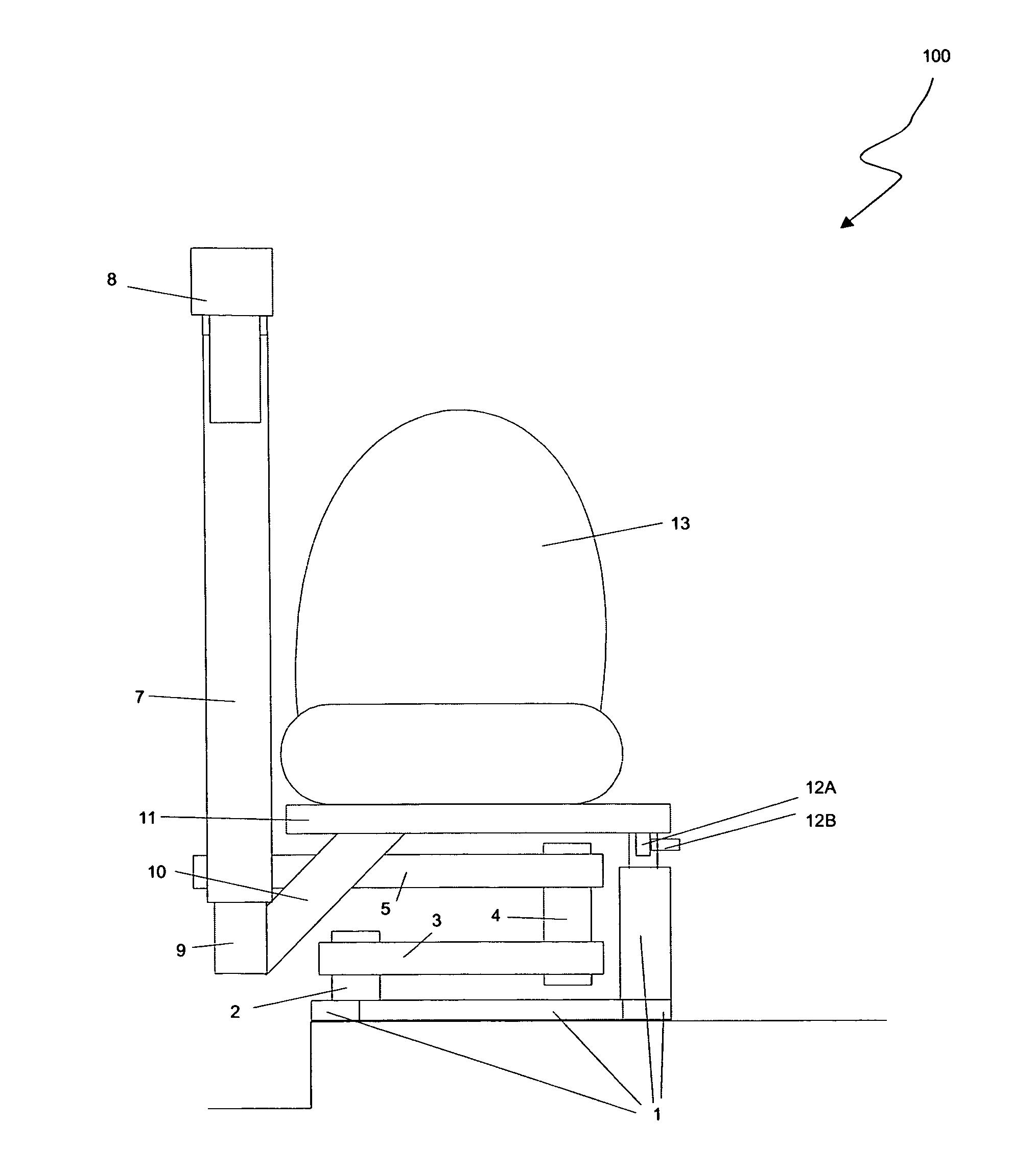
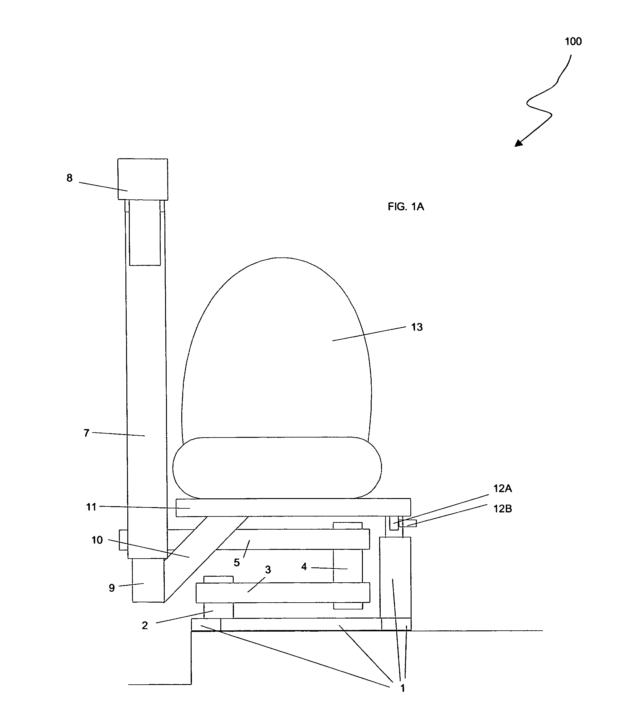
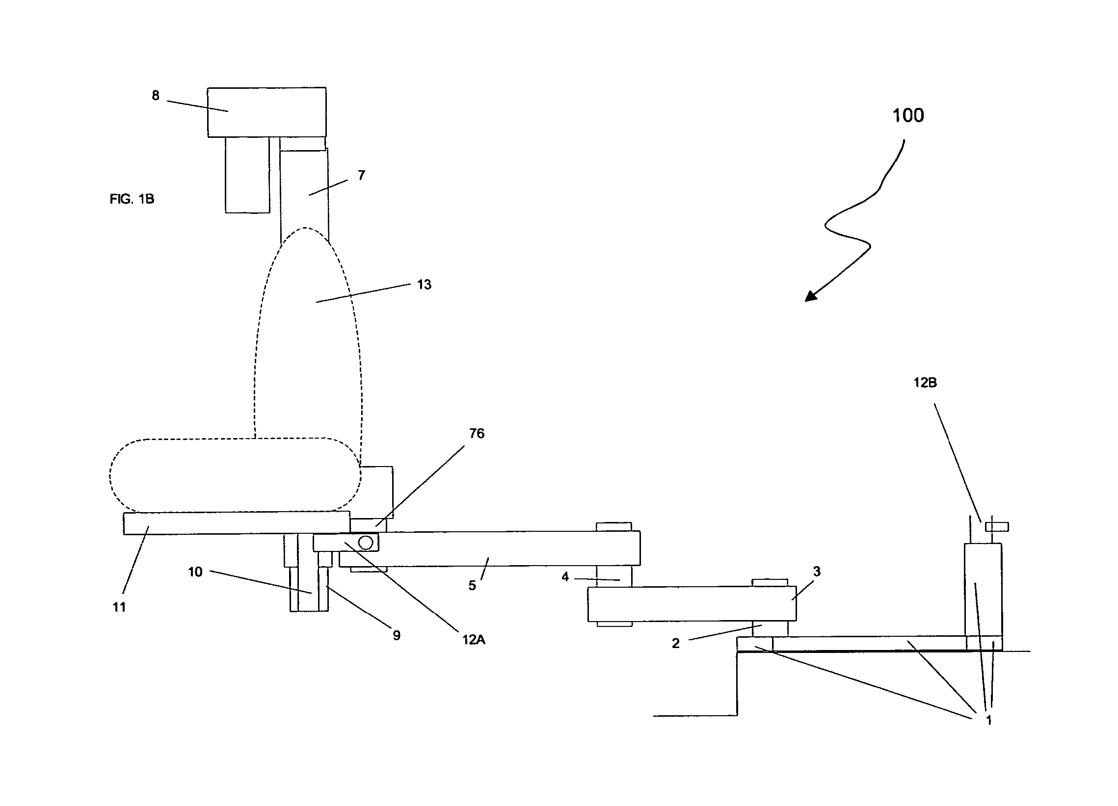
[0031]Referring to FIGS. 1A-1C, there is shown a multi-motion lifting and transferring apparatus 100 in accordance with an embodiment of the present disclosure in three respective positions. Beginning from the bottom of the apparatus 100 upward, the apparatus 100 includes a base support assembly 1 for securely mounting the apparatus 100 to, for example, the floor of a vehicle or other structure. The apparatus 100 also includes a pivot point 2 allowing horizontal support member 3 to pivot about a substantially vertical axis. Pivot point 4 allows horizontal support member 5 to pivot about a substantially vertical axis. Pivot point 6 allows up / down extension arm outer support sleeve 7 to pivot about a substantially vertical axis. Thus, all support members and the up / down extension arm are allowed to pivot freely throughout a 360 degree rotation unless impaired by vehicle structural elements or interference from other apparatus structures.

[0032]The up / down extension arm outer support sl...


PUM


Abstract

A multi-motion lifting and transferring apparatus and method are disclosed. The multi-motion lifting and transferring apparatus and method may be realized in primarily two versions, the first being referred to as the single linkage arm version, and the second being referred to as the dual linkage arm version. In one particular exemplary embodiment, a multi-motion lifting and transferring apparatus in accordance with the single linkage arm version may be realized as having a first pivot point for rotating an intermediary support member about a first substantially vertical axis, a second pivot point for rotating an electrically or hydraulically powered up / down extension arm about a second substantially vertical axis, and a seat support member for supporting a seat for accommodating at least one person.

Description

CROSS-REFERENCE TO RELATED APPLICATIONS[0001]This patent application claims priority to U.S. Provisional Patent Application No. 60 / 561,552, filed Apr. 13, 2004, which is hereby incorporated by reference herein in its entirety.FIELD OF THE DISCLOSURE[0002]The present disclosure relates generally to devices and methods for lifting and transferring persons into and out of vehicles and, more particularly, to a multi-motion lifting and transferring apparatus and method for assisting persons when entering and exiting a vehicle.BACKGROUND OF THE DISCLOSURE[0003]Difficulties are often encountered when transferring disabled persons from one location to another. Particularly in the case of wheelchair-bound persons, it is often quite difficult to lift and transfer such persons to and from their wheelchair from and to, for example, a motor vehicle. One or more persons are usually required to assist the disabled person.[0004]There have been some inventive efforts directed at alleviating the prob...

Claims


Application Information

Patent Timeline
Patent Type & Authority Patents(United States)
IPC IPC(8): B60P1/00B60N2/00B60N2/02B60N2/14B60N2/24B60N2/50
CPCB60N2/14B60N2/245Y10S414/134
Inventor EGAN, THOMAS F.
Owner EGAN THOMAS F
Why Eureka
Try Eureka