Oral treatment device

a treatment device and oral tube technology, applied in the field of oral treatment devices, can solve the problems of undesirable, bulky, rigid and bulky available systems

Active Publication Date: 2017-06-22
COLGATE PALMOLIVE CO
View PDF16 Cites 26 Cited by
  • Summary
  • Abstract
  • Description
  • Claims
  • Application Information

AI Technical Summary

Benefits of technology

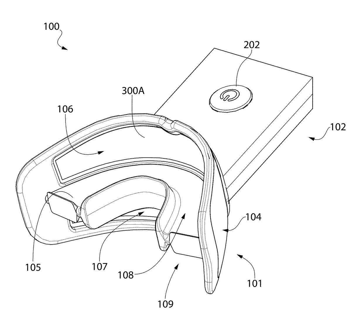
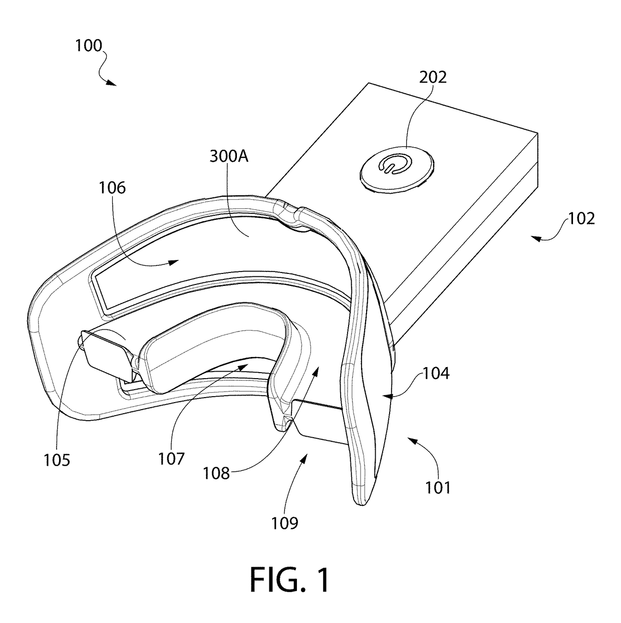
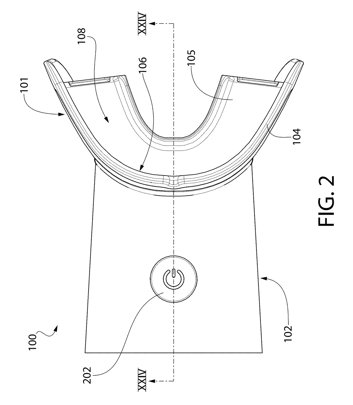
[0003]In one aspect, the invention may be an oral treatment device comprising: an intraoral mouthpiece comprising: a lamp support structure comprising a lamp support surface having a concave curvature and a front surface having a convex curvature, the lamp support structure formed of a first material; a lamp comprising: a flexible sheet body having a front surface and a rear surface; and a plurality of light emitters embedded within the flexible sheet body that generate light which is emitted from the rear surface of the flexible sheet body; the lamp mounted to the lamp support surface of the lamp support structure so that the rear surface of the flexible sheet body of the lamp assumes a concave curvature, thereby forming a lamp assembly, the lamp operably coupled to a control circuit having a power source; and a guard component overmolded to the lamp assembly, the guard component formed of an elastomeric material having a hardness that is less than a hardness of the first material.
[0004]In another aspect, the invention may be an oral treatment device comprising: an intraoral mouthpiece comprising: a lamp support structure comprising a lamp support surface; first and second lamps, each of the first and second lamps comprising a plurality of light emitters that generate light which is emitted from a rear surface of the lamp; each of the first and second lamps mounted to the lamp support surface, thereby forming a lamp assembly, each of the first and second lamps operably coupled to a control circuit having a power source; and a lamp retaining component coupled to the lamp support structure, a lower portion of the first lamp and an upper portion of the second lamp retained between the lamp retaining component and the lamp support surface of the lamp support structure.
[0005]In yet another aspect, the invention may be an oral treatment device comprising: an intraoral mouthpiece comprising: a lamp support surface; first and second electrical contact elements electrically coupled to a control circuit having a power source, the first electrical contact element comprising a first contact surface and the second contact element comprising a second contact surface, each of the first and second contact surfaces of the first and second contact elements forming a portion of the lamp support surface; a lamp comprising: a plurality of light emitters that generate light which is emitted from a rear surface of the lamp; and first and second electrical contacts, the first electrical contact having a first contact surface that forms a first portion of a front surface of the lamp, and the second electrical contact having a second contact surface that forms a second portion of the front surface of the lamp; and the lamp mounted to the lamp support surface so that: (1) the first contact surface of the first electrical contact of the lamp contacts the first contact surface of the first electrical contact element; and (2) the second contact surface of the second electrical contac...

Problems solved by technology

However, currently available systems are bulky and rigid and undesirable for one or more reasons, s...

Method used


Image

  • Oral treatment device
  • Oral treatment device
  • Oral treatment device

Examples


Embodiment Construction

[0048]The following description of the preferred embodiment(s) is merely exemplary in nature and is in no way intended to limit the invention, its application, or uses.

[0049]The description of illustrative embodiments according to principles of the present invention is intended to be read in connection with the accompanying drawings, which are to be considered part of the entire written description. In the description of embodiments of the invention disclosed herein, any reference to direction or orientation is merely intended for convenience of description and is not intended in any way to limit the scope of the present invention. Relative terms such as “lower,”“upper,”“horizontal,”“vertical,”“above,”“below,”“up,”“down,”“top” and “bottom” as well as derivative thereof (e.g., “horizontally,”“downwardly,”“upwardly,” etc.) should be construed to refer to the orientation as then described or as shown in the drawing under discussion. These relative terms are for convenience of descripti...


PUM


Abstract

An oral treatment device that emits light onto surfaces of a user's teeth. In one aspect, the oral treatment device includes an intraoral mouthpiece. The mouthpiece comprises: a first light emitting surface configured to emit light onto a user's maxillary teeth, the first light emitting surface having a concave curvature; a second light emitting surface configured to emit light onto a user's mandibular teeth, the second light emitting surface having a concave curvature; the first and second light emitting surface located on opposite sides of a horizontal reference plane; the first light emitting surface inclined so that a first acute angle is formed between with the first light emitting surface and the horizontal reference plane; and the second light emitting surface inclined so that a second acute angle is formed between with the second light emitting surface and the horizontal reference plane.

Description

BACKGROUND[0001]Oral treatments, such as tooth whitening, are an increasingly popular treatment. Dentists and patients alike are searching for techniques that are both convenient and comfortable. Typically, to whiten a user's teeth a composition containing hydrogen peroxide is applied to the teeth and allowed to remain in contact with the teeth to be bleached for a period of time. Current systems are available that allow a user to apply radiation or light to the surfaces of the teeth that are pre-coated with the whitening composition to enhance the effectiveness of the whitening composition. However, currently available systems are bulky and rigid and undesirable for one or more reasons, such as requiring complex head mounting gear, being hand-held, or requiring a furniture-like mounted lamp. Specifically, current systems do not emit radiation or light onto the user's pre-coated teeth uniformly and in a manner that effectively covers the entire tooth surface. Thus, a need exists for...

Claims


Application Information

Patent Timeline
IPC IPC(8): A61N5/06A61C19/06A61C5/14
CPCA61N5/0603A61C5/14A61C19/066A61N5/062A61N2005/0668A61N2005/0606A61N2005/0644A61N2005/0654A61N5/0624A61C19/003
Inventor DEMAREST, SCOTTTATU, FRANCISBARTLETT, MARKDELGADO, EVARISTONEAL, KATHRYNJOHANSSON, PATRIKLOWENTHAL, MARK
Owner COLGATE PALMOLIVE CO
Why Eureka
Try Eureka