Conveying systems

a technology of conveying system and material, applied in the field of conveying system, can solve the problems of consuming a large amount of energy, reducing the life of the system, and reducing the efficiency of the system, so as to achieve smooth and continuous conveying of materials, and reducing the energy consumption of breaking the bridge.

Active Publication Date: 2017-06-22
DYNAMIC AIR
View PDF35 Cites 0 Cited by
  • Summary
  • Abstract
  • Description
  • Claims
  • Application Information

AI Technical Summary

Benefits of technology

The patent is about a system that can clear blockages in a conveyor system caused by materials sticking together and forming a bridge. The system uses air pressure to disintegrate the bridge and allow the materials to flow through the conveyor. This can be done by releasing air into the bottom of the conveyor and allowing it to flow upwards through the materials to dislodge any bridges. The system is efficient and requires no additional devices, minimizing energy consumption. The technology can be repeated as needed to keep the conveyor running smoothly.

Problems solved by technology

One of the difficulties with delivering conveyable materials through a gravity hopper is that often times the particles of the conveyable materials may adhere to one another and form a self supporting bridge over the outlet in the gravity hopper thus preventing flow of the conveyable materials through the hopper outlet.
U.S. Pat. No. 3,195,775 shows an example of a device that vibrates a hopper to break a material bridge in a hopper, unfortunately vibration of the hopper can prematurely decrease the life of the system as well as consume a large amount of energy.
This type of device requires a large amount of energy to break up the bridge and has been referred to as the creation of a “dull explosion” in the material.
As can be seen from the above prior art it is difficult to continuously convey bridgeable materials due to the problem of bridging of conveyable materials, which has given rise to numerous methods and apparatus.
Compounding the problem of conveyable materials, which may bridge, is that some bridges within the hopper may be broken easily while others are extremely difficult to break up.
The prior methods have certain disadvantages in that some methods may substantially increase noise level proximate the hopper, some may shorten the life of the system, some may require large amounts of energy or some require multiple air blasters or bin aerators mounted to the sides of the hopper, which increases both the complexity and costs of the system.
In some cases the prior art methods are simply ineffective and instead of dislodging bridged material an air blaster may form a “rat hole” in the bridged material, which is a passageway from the blaster to the hopper outlet that does not break up the bridge but prevents the bridged material from falling into the hopper outlet.

Method used


Image

  • Conveying systems
  • Conveying systems
  • Conveying systems

Examples


Embodiment Construction

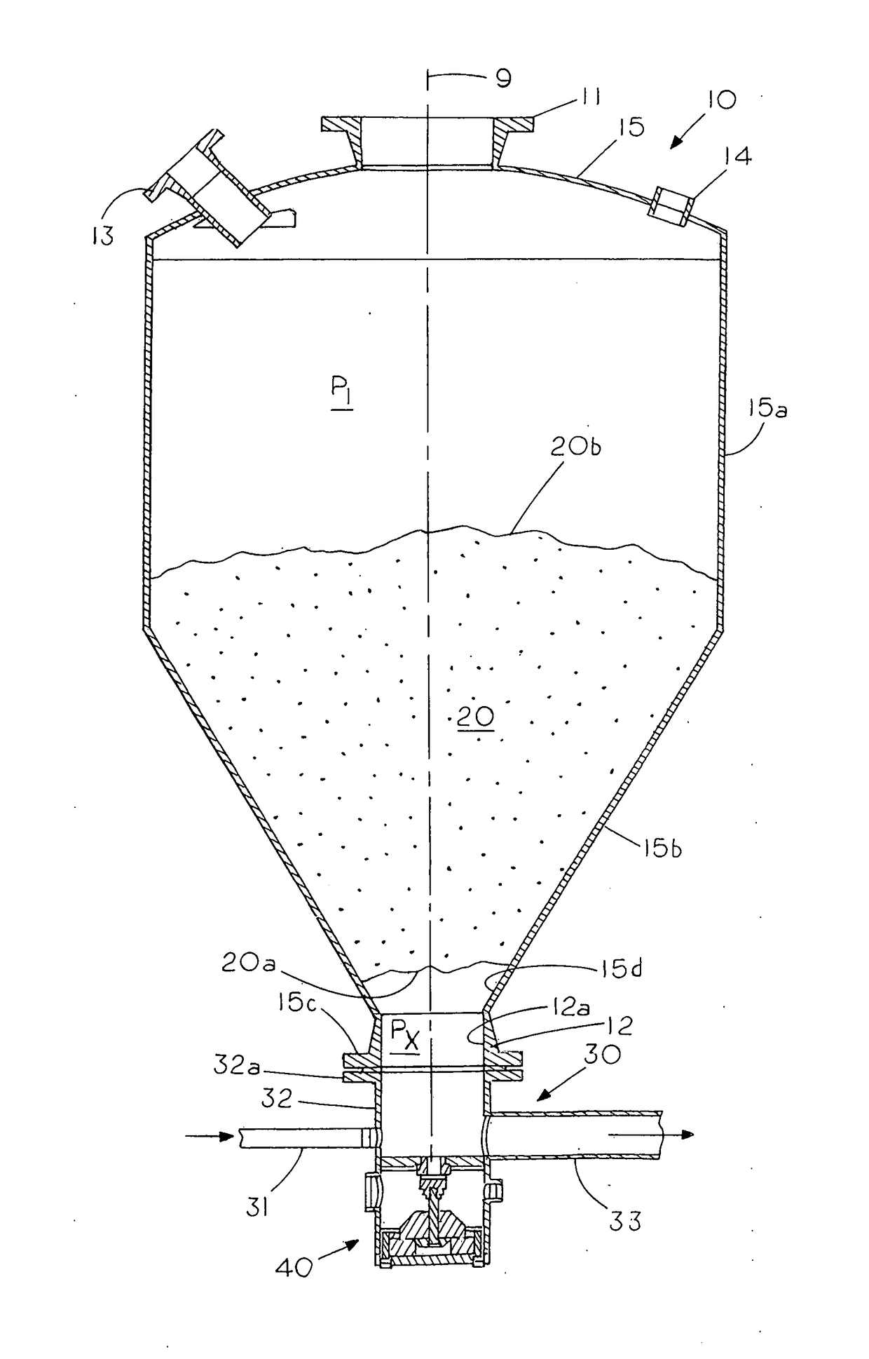
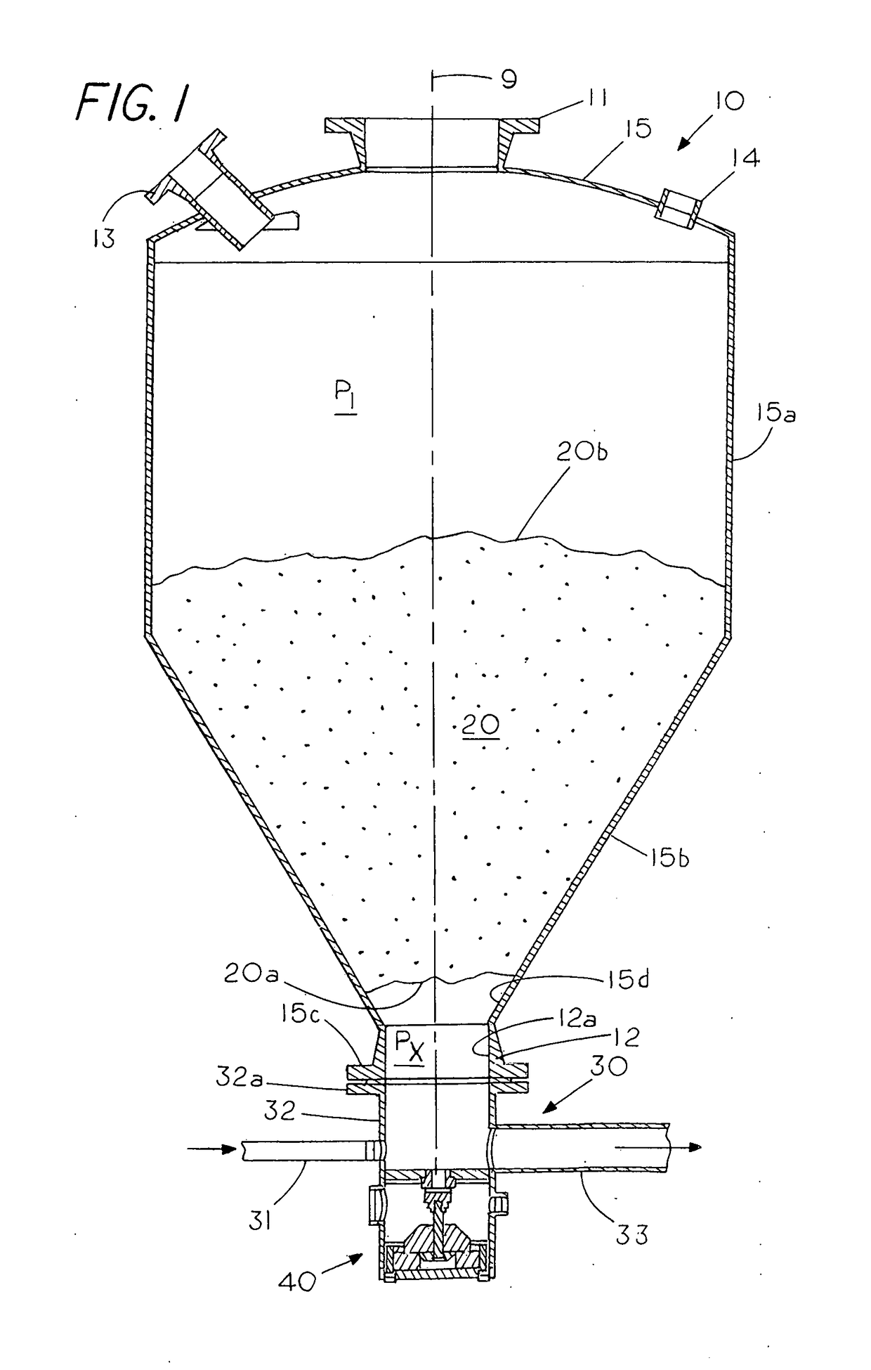
[0020]FIG. 1 shows a cylindrical gravity hopper 10 having a vertical axis 9 extending through a cylindrical hopper inlet 11 located at the top of the hopper and a cylindrical downward facing hopper outlet 12 located at the bottom of the hopper. Hopper 10 includes a domed top 15 with a port 13, a port 14 and hopper inlet 11 located therein. In this example hopper 10 includes a cylindrical sidewall 15a and an intermediate open-ended cone 15b that converges from cylindrical sidewall 15a to a cylindrical hopper outlet 12, which has a cylindrical vertical sidewall 12a for directing material away from and out of the hopper 10. A flange 15c on outlet 12 allows one to secure a conveying system 30 to hopper outlet 12. Typically, one directs a batch of conveyable material into the hopper inlet 11 of the gravity hopper 10 where the conveyable material is gravitationally funneled to the hopper outlet 12 located at the bottom of the hopper 10. The conveyable material discharging from the hopper ...


PUM


Abstract

A conveying system for conveying a conveyable material from a hopper where the system includes a fluid port located below the hopper outlet and in a vertical flow path into hopper outlet that can be momentarily opened for an on the go release of a charge of compressed air directly upward into the hopper outlet and into the underside of the bridge in the hopper to either disintegrate or unlock the bridged particles from each other thereby causing the bridged material to fall into the hopper outlet and into the conveying system where the material can be transported to a remote location or to remove any material that may be adhering to the wall during an emptying phase.

Description

CROSS REFERENCE TO RELATED APPLICATIONS[0001]NoneSTATEMENT REGARDING FEDERALLY SPONSORED RESEARCH OR DEVELOPMENT[0002]NoneREFERENCE TO A MICROFICHE APPENDIX[0003]NoneBACKGROUND OF THE INVENTION[0004]This invention relates generally to conveying systems and, more specifically, to a conveying system and a low energy method of maintaining a flow of conveyable material that is subject to bridging.[0005]In conveying solid materials, which may comprise a variety of solid materials or particles, the conveyable materials are typically delivered to a gravity hopper, which contains a cone shaped base that directs the conveyable material to an outlet at the bottom of the gravity feeder. Typically, the outlet connects to a conveying line such as a pneumatic or mechanical conveying line, which conveys the material to a different location. One of the difficulties with delivering conveyable materials through a gravity hopper is that often times the particles of the conveyable materials may adhere ...

Claims


Application Information

Patent Timeline
Patent Type & Authority Applications(United States)
IPC IPC(8): B65D88/70B65D88/26B65G65/40B65G3/04B65G53/04
CPCB65D88/703B65G3/04B65D88/26B65G65/40B65G53/04B65G53/10B65G53/42B65G53/66B65D88/54
Inventor STEELE, JAMES
Owner DYNAMIC AIR
Why Eureka
Try Eureka