
Bearing arrangement for a wind turbine

a technology for wind turbines and bearings, applied in sliding contact bearings, mechanical equipment, machines/engines, etc., can solve the problems of affecting the overall length of the bearing, affecting the lubrication of the bearing, so as to achieve the effect of improving the overall length and improving the mounting

Active Publication Date: 2017-06-06
SIEMENS GAMESA RENEWABLE ENERGY AS
View PDF19 Cites 0 Cited by
  • Summary
  • Abstract
  • Description
  • Claims
  • Application Information

AI Technical Summary

Benefits of technology

The patent text explains that the invention prevents damage to the lubrication in a bearing and the bearing itself by electrically isolating the first bearing shell from the first part of the wind turbine. This is done by regularly measuring the current flow and performing the measurement every 5 minutes, for example, which minimizes energy usage.

Problems solved by technology

Such a main bearing is a major component of a direct drive wind turbine making up a considerable portion of total cost of the wind turbine.
The exchange of such a main bearing bears extensive effort and cost, including a lifting operation to detach the hub from the bearing and gain access to the bearing.
Also a static charge present in the bearing can lead to damage of the lubricant, especially due to electrolysis.
These can damage the lubrication of the bearing and can lead to a higher friction in the bearing.
This can also lead to a damage of the surface of the bearing components by erosion and decomposition.
This leads to mechanical problems in the bearing, like higher wear, thus the lifetime and the reliability of the bearing is reduced and the cost of service and maintenance are increased.
This leads to short but strong current flowing through the bearing.
This will lead to the same mechanical problems as described above.
If there is a failure in the connections of the high voltage conductor, the current of the lightning strike will lead through the bearing.
Even if there is no failure, there is a certain possibility that the lightning will not choose the high voltage connection.
All these solutions show the disadvantage of unreliability.
The solutions mentioned above might get damaged by a first lightning strike and might lead to a current flowing through the bearing thereafter.
The isolation ring is needed to prohibit lightning to flow over the bearing, as this would damage the lubrication and the bearing.
In addition a possible creeping current running through the bearing is limited.

Method used


Image

  • Bearing arrangement for a wind turbine
  • Bearing arrangement for a wind turbine
  • Bearing arrangement for a wind turbine

Examples


Embodiment Construction

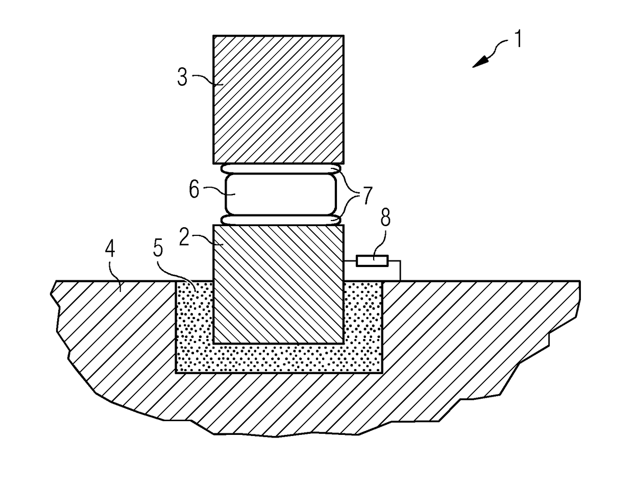
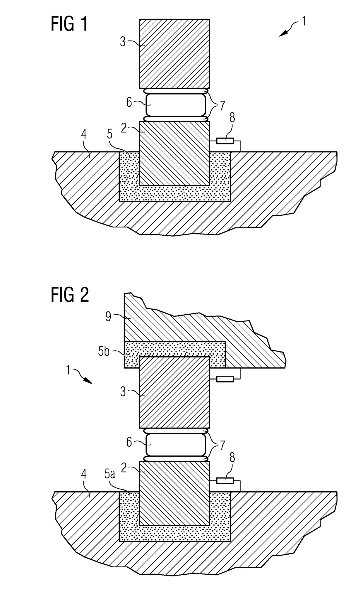
[0094]FIG. 1 shows a radial cut through one side of the ring-shaped bearing arrangement 1.

[0095]The bearing arrangement 1 comprises a first bearing shell 2 and a second bearing shell 3. The bearing shells 2 and 3 are arranged in a way that they are movable in respect to each other to allow a rotation of the bearing.

[0096]The second bearing shell 3 holds for example a rotor of a direct drive generator with permanent magnets and a hub with rotor blades. The second bearing shell 3 is electrically connected to a first part of the wind turbine 4 and connected to electric reference ground.

[0097]In this case the first bearing shell 2 is connected to a first part of the wind turbine 4. Between the first bearing shell 2 and the first part of the wind turbine 4 is an isolation ring 5. The first bearing shell 2 and the first part of the wind turbine 4 can be mechanically connected through electrically isolated bolts. The isolation ring 5 isolates the first bearing shell 2 electrically from the...


PUM


Abstract

A bearing arrangement to avoid a static charge in a bearing is provided.A bearing arrangement for a wind turbine comprises a first bearing shell that is prepared to be coupled to a first part of the wind turbine. The bearing arrangement comprises a second bearing shell that is prepared to be coupled to a second part of the wind turbine. The first and the second bearing shell are arranged in a way that the first and the second bearing shell are rotatable with respect to each other and have a first isolation ring for electrical isolation, so that the first part of the wind turbine can be rotated with respect to the second part of the wind turbine and avoid static discharge.

Description

CROSS-REFERENCE TO RELATED APPLICATIONS[0001]This application claims priority to PCT Application No. PCT / EP2012 / 056669, having a filing date of Apr. 12, 2012, based off of EP Application No. 12152812.9, having a filing date of Jan. 27, 2012, the entire contents of which are hereby incorporated by reference.FIELD OF TECHNOLOGY[0002]The following relates to a bearing arrangement to avoid a static charge in a bearing.BACKGROUND[0003]A bearing is a common part in machinery like wind turbines. Bearings are used to separate a rotating part of the machinery from a stationary part of the machinery. Bearings allow the rotation of the rotating part in respect to the stationary part while at the same time minimizing the friction between the two parts.[0004]In wind turbines, bearings are used for several functions. In geared wind turbines, several bearings are used within the drive train for the hub, the main shaft, the gearbox and the generator. Bearings are also used in a wind turbine to allo...

Claims


Application Information

Patent Timeline
Patent Type & Authority Patents(United States)
IPC IPC(8): F03D80/00F03D80/30F03D80/70F16C17/24
CPCF03D80/00F03D80/30F03D80/70F16C17/24Y02E10/72F16C2360/31
Inventor NIEUWENHUIZEN, JOHN
Owner SIEMENS GAMESA RENEWABLE ENERGY AS
Learn More