Underwater lighting device

a lighting device and underwater technology, applied in the direction of lighting heating/cooling arrangement, lighting protection devices, lighting and heating apparatus, etc., can solve the problems of deteriorating electronic boards and light-emitting devices, weak device of the state of the art, and increasing etc., to improve the heat transfer effect and increase the heat conductivity of resin layers

Inactive Publication Date: 2017-06-22
SIELED
View PDF6 Cites 11 Cited by
  • Summary
  • Abstract
  • Description
  • Claims
  • Application Information

AI Technical Summary

Benefits of technology

[0021]the sealing of the protective cover with the heat exchange surface to prevent the coming into contact of the electronic board and of the light-emitting means with the aquatic environment.
[0051]Thus, such a resin layer enables to protect the electronic board from deformations linked to the outer pressure of the aquatic environment.

Problems solved by technology

Indeed, in the absence of heat transfer means, it can be observed that the temperature of the electronic board strongly increases, which may deteriorate the electronic board and the light-emitting means in case of an extended operation of the device.
However, such a device of the state of the art is not fully satisfactory since it requires a conical seal, typically made of rubber, arranged between the metal plate and the protective cover, to prevent the coming into contact of the electronic board and of the light-emitting means with the aquatic environment.
The forming of shoulders in the protective cover also results in the forming of shoulders in the metal plate.
Accordingly, such a device of the state of the art introduces a complexity in the manufacturing thereof by specific machinings of the protective cover and of the metal plate.
The seal undergoes compressive losses due to differential expansions with respect to the metal plate, which adversely affects the lifetime of the seal, and thereby of the device.

Method used


Image

  • Underwater lighting device
  • Underwater lighting device
  • Underwater lighting device

Examples


Embodiment Construction

[0075]For the different embodiments, the same references will be used for identical elements or elements performing the same function, to simplify the description. The technical characteristics described hereafter for different embodiments are to be considered separately or according to any technically possible combination.

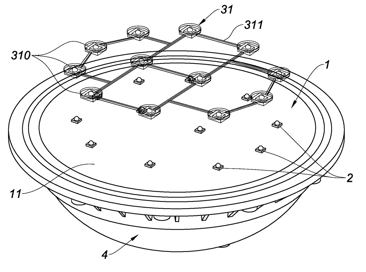
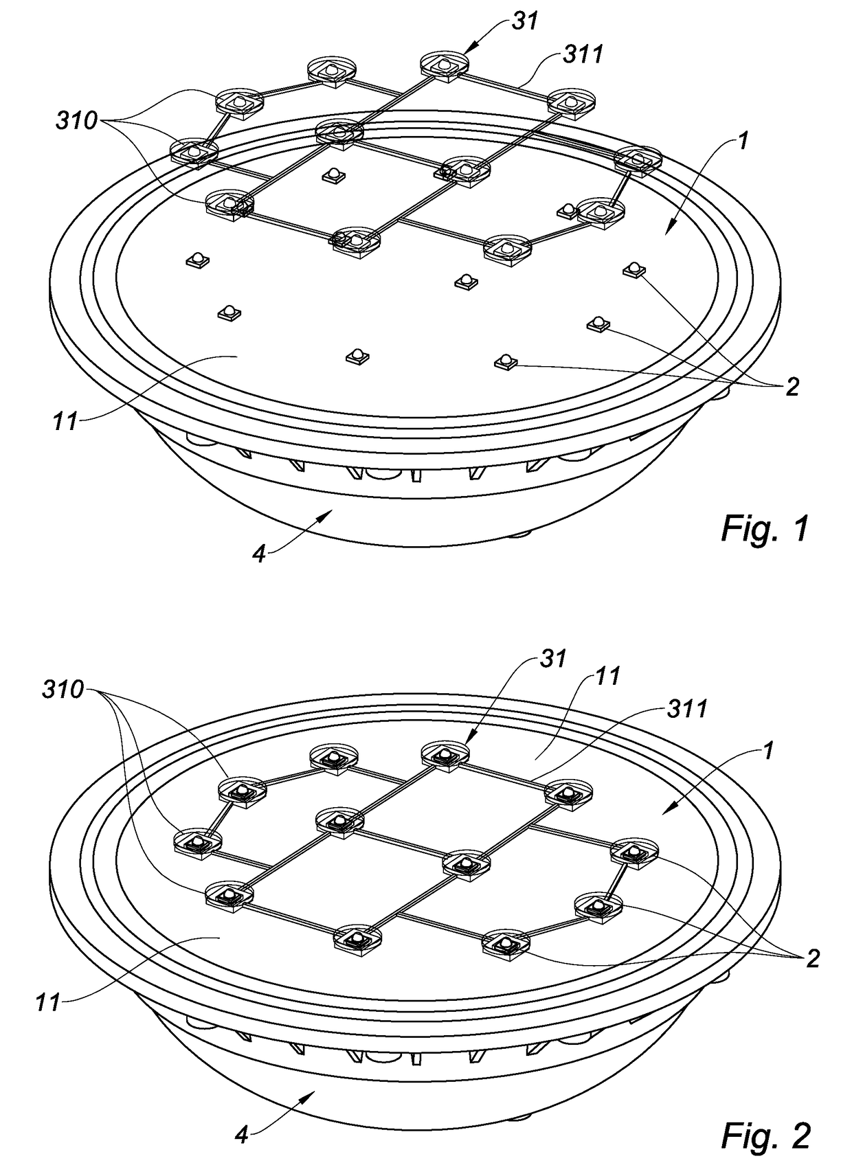
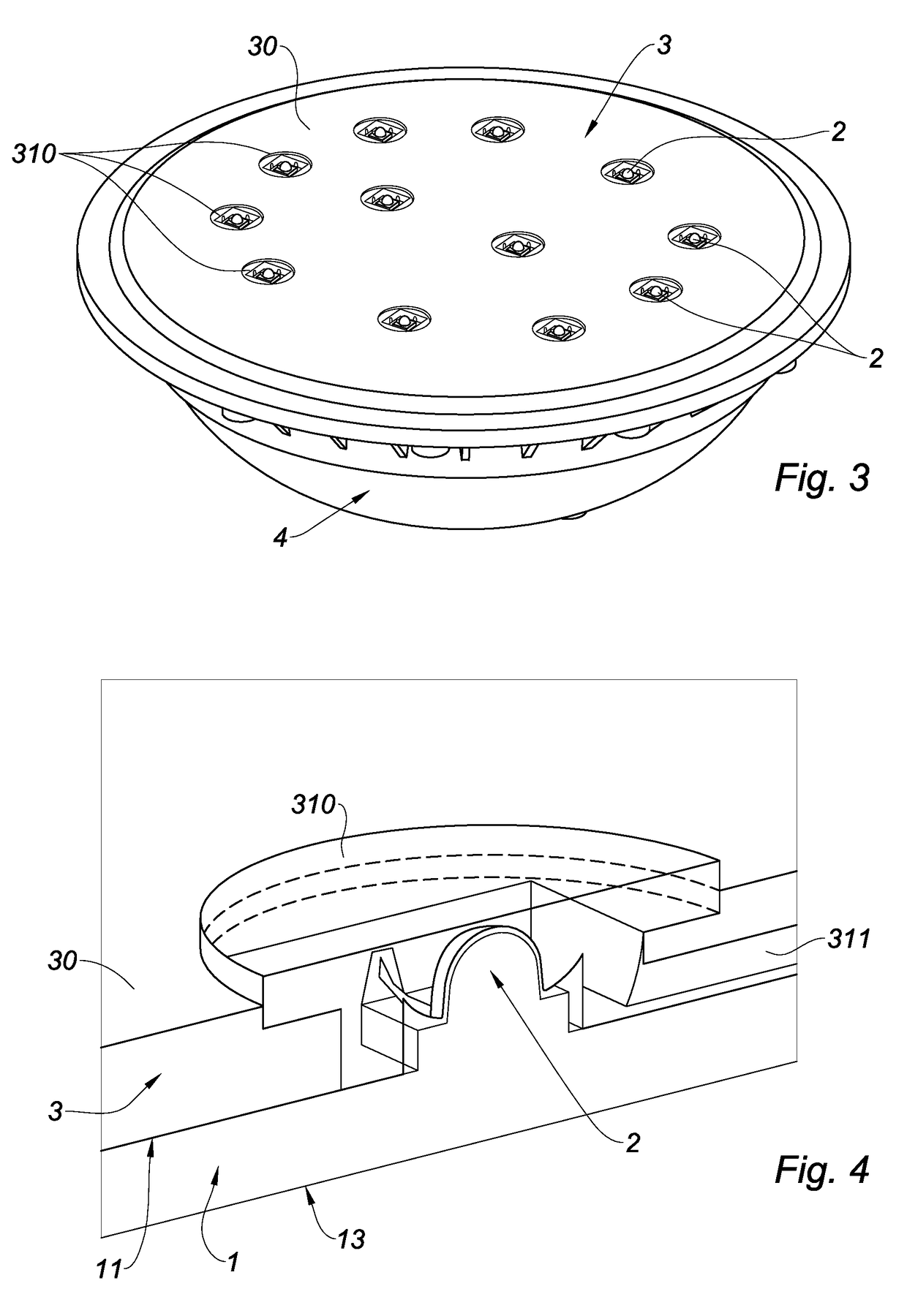
[0076]The first device illustrated in FIGS. 1 to 4 is an underwater lighting device, comprising:

[0077]an electronic board 1 comprising a surface, called front surface 11,

[0078]light-emitting means 2, preferably of light-emitting diode type, assembled on front surface 11 of electronic board 1,

[0079]a protective cover 4 arranged to protect electronic board 1 and light-emitting means 2,

[0080]heat transfer means for transferring the heat generated by light-emitting means 2 to the aquatic environment.

[0081]Electronic board 1 comprises a circuit for controlling light-emitting means 2. Electronic board 1 preferably is in the shape of a disk. As a non-limiting example, el...


PUM

PropertyMeasurementUnit
thicknessaaaaaaaaaa
heightaaaaaaaaaa
heightaaaaaaaaaa

Abstract

This device includes an electronic board including a front surface; at least one light emitter assembled on the front surface; a protective cover configured to protect the electronic board and the at least one light emitter; a thermally-conductive resin layer having a heat exchange surface meant to be in direct contact with the aquatic environment, the thermally-conductive resin layer being configured to transfer the heat generated by the at least one light emitter to the heat exchange surface, and configured to ensure the sealing of the protective cover with the heat exchange surface.

Description

TECHNICAL FIELD[0001]The present invention relates to an underwater lighting device.BACKGROUND ART[0002]An underwater lighting device known in the state of the art, particularly from document EP 2 594 245, comprises:[0003]an electronic board comprising a surface, called front surface,[0004]light-emitting means assembled on the front surface of the electronic board,[0005]a protective cover arranged to protect the electronic board and the light-emitting means,[0006]heat transfer means arranged to transfer the heat generated by the light-emitting means to the aquatic environment.[0007]The heat transfer means comprise a metal plate assembled on the surface, called rear surface, opposite to the front surface of the electronic board. The metal plate is intended to be submerged in the aquatic environment to benefit from a heat exchange with the aquatic environment in order to be cooled. The metal plate thus enables to dissipate the heat essentially generated by the light-emitting means, su...

Claims


Application Information

Patent Timeline
Patent Type & Authority Applications(United States)
IPC IPC(8): F21V31/00F21V29/70F21V11/00F21V15/00
CPCF21V31/00F21V11/00F21V29/70F21V15/00F21V5/007F21V23/005F21V29/506F21V29/507F21V29/56F21V29/83F21V3/062F21V3/061F21V5/04
Inventor GUILLET, CHRISTIANPELLATON, PATRICK
Owner SIELED
Why Eureka
Try Eureka