
Suture tape construct for providing anchor with non-sliding suture tape

a construction and suture tape technology, applied in the field of sutures, can solve problems such as large irritating knots

Active Publication Date: 2017-06-29
CONMED CORP
View PDF4 Cites 4 Cited by
  • Summary
  • Abstract
  • Description
  • Claims
  • Application Information

AI Technical Summary

Benefits of technology

The present invention is a suture anchor that has two sections: a first section and a second section. The second section is moveable between an extended position and a deployed position. The first section is made of suture tape and the second section is made of braided suture material. The second section can also be made of other objects, such as flat woven material or cannulation. The suture anchor is designed to prevent any movement of the second section relative to the first section, using protrusions that are woven into the suture tape of the first section. This suture anchor is effective in providing fixation to bone and can be easily deployed by inserting it into a hole in bone and pulling the ends of the first section until the second section moves from the extended position to the deployed position.

Problems solved by technology

A drawback of using suture tape is that knots formed from suture tape are larger than knots of round suture and thus are often avoided to reduce the chance of post-operative pain.
If a double row repair is attempted with suture tape, however, the surgeon must either tie a horizontal mattress stitch with the suture tape, thus leaving a large irritating knot, or avoid the use of horizontal mattress stitch, thus leaving the suture free to slide and requiring additional steps that could potentially cause damage.

Method used


Image

  • Suture tape construct for providing anchor with non-sliding suture tape
  • Suture tape construct for providing anchor with non-sliding suture tape
  • Suture tape construct for providing anchor with non-sliding suture tape

Examples


Embodiment Construction

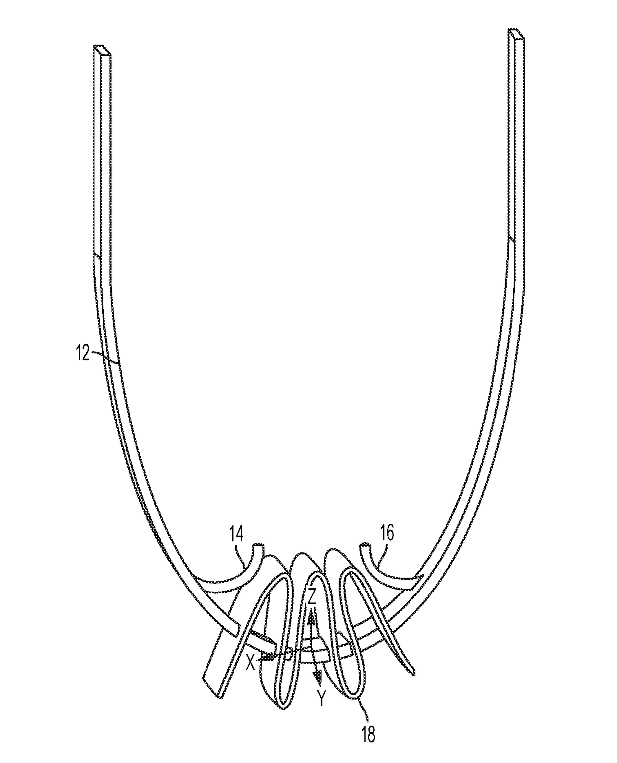
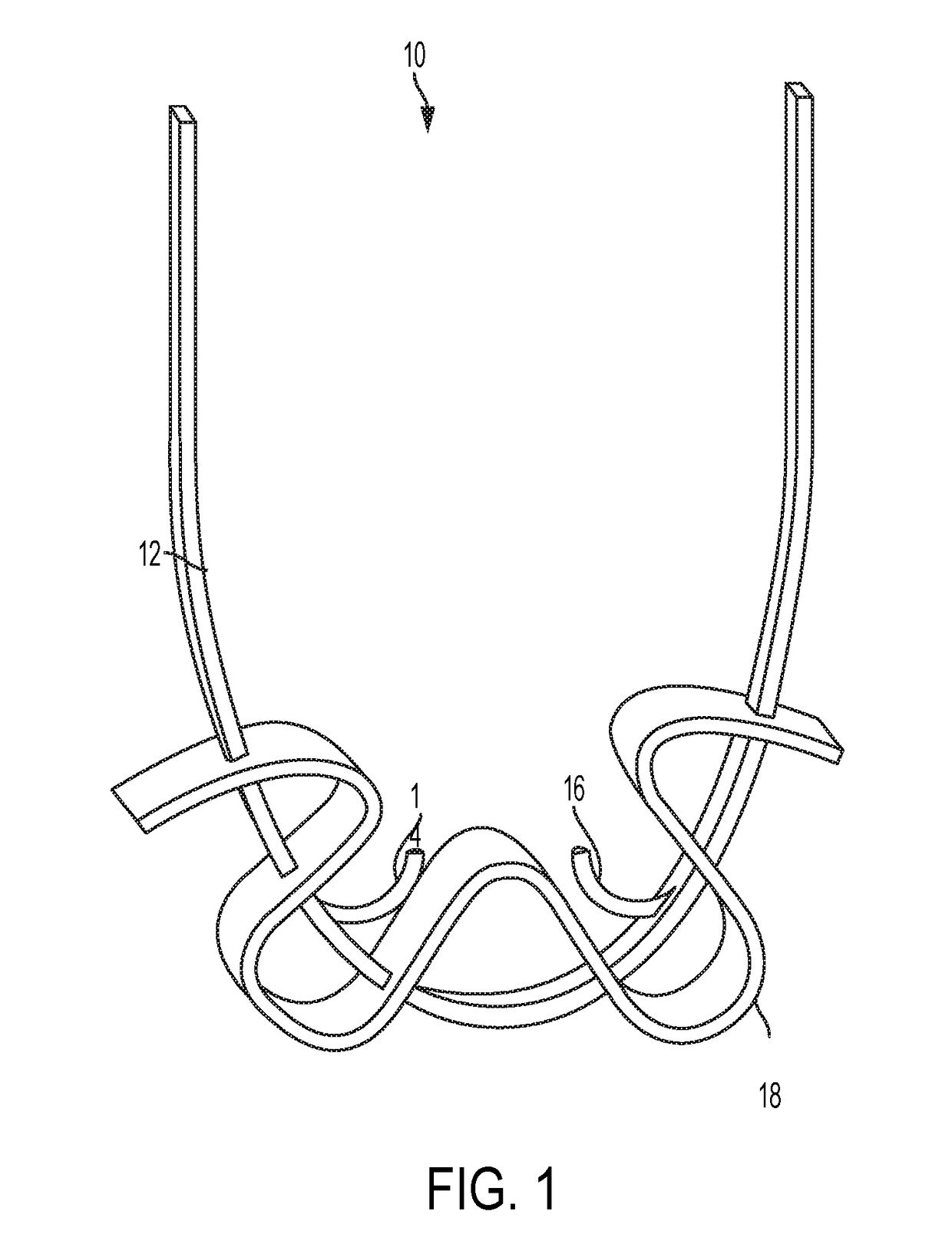
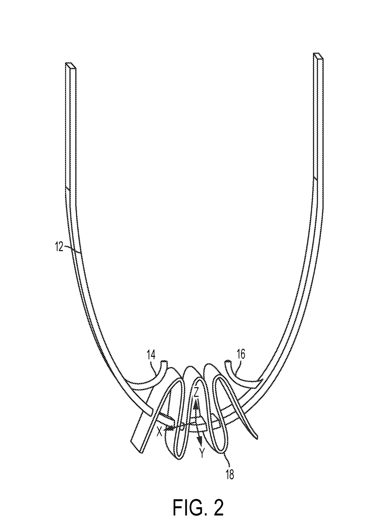
[0016]Referring now to the drawings, wherein like reference numerals refer to like parts throughout, there is seen in FIG. 1 a non-sliding suture construct 10 comprising a length of fibrous filament (which can be suture tape) 12 having a pair of protrusions 14 and 16 extending outwardly therefrom. A length of flat braided material 18 serving as a suture anchor is positioned along fibrous filament 12, i.e., fibrous filament 12 has been woven through braided material 18. For example, material 18 may be folded several times with fibrous filament 12 passing through each fold. In the depicted embodiment, braided material 18 has six punctures to receive suture fibrous filament 12; however, four punctures or eight punctures can be used (or any other number of punctures can be used as may be required for application of the non-sliding suture construct, as should be appreciated by a person of ordinary skill in the art in conjunction with a review of this disclosure). In accordance with an em...


PUM


Abstract

A suture tape construct having a first section formed from a fibrous filament that extends from a first end to a second end and has a pair of a one-way protrusions extending therefrom. An anchor is positioned along the suture construct and, when the construct is deployed, is captured between the protrusions. The anchor may be a second section formed from braided suture material that is woven about the first section. The braided suture material can be deployed to form an all suture anchor while protrusions extending from the suture anchor proximately to the location of the deployed suture anchor prevent movement of the second section relative to the first section, thus forming a non-sliding suture tape anchored by the deployed braided material. The anchor may be a threaded anchor having an eyelet that is captured between the protrusions.

Description

CROSS REFERENCE TO RELATED APPLICATIONS[0001]The present application relates and claims priority to U.S. Provisional Application Ser. No. 62 / 271,401 filed Dec. 28, 2015, the entirety of which is hereby incorporated by reference.BACKGROUND OF THE INVENTION[0002]1. Field of the Invention[0003]The present invention relates to sutures and, more specifically, to a suture construct having non-sliding suture tape capturing a suture anchor.[0004]2. Description of the Related Art[0005]In soft tissue to bone repair procedures, such as rotator cuff repair, round sutures have commonly be used to hold soft tissue to bone in surgical procedures. An increasingly common practice, however, is to use what is referred to as suture tape, a generally flat material of woven fibers. Suture tape is considered advantageous for use in certain procedures such as rotator cuff repairs because it can promote increased tissue-to-bone contact area and can more evenly distribute pressure compared to round suture. A...

Claims


Application Information

Patent Timeline
Patent Type & Authority Applications(United States)
IPC IPC(8): A61B17/04
CPCA61B17/0401A61B2017/0464A61B2017/0414A61B2017/0412A61B17/06166A61B2017/0403A61B2017/0406A61B2017/044A61B2017/06176
Inventor BRESLICH, GRADY
Owner CONMED CORP
Learn More