Lighting apparatus, automobile, and projection lens

a technology of projection lens and lighting apparatus, which is applied in the direction of fixed installation, lighting and heating apparatus, transportation and packaging, etc., can solve the problems of inability to ensure sufficient illuminance in the left and right regions of the field of view, and the driver cannot easily spot pedestrians, so as to achieve sufficient illuminance and inhibit glare

Active Publication Date: 2017-06-29
PANASONIC INTELLECTUAL PROPERTY MANAGEMENT CO LTD
View PDF2 Cites 6 Cited by
  • Summary
  • Abstract
  • Description
  • Claims
  • Application Information

AI Technical Summary

Benefits of technology

[0007]Light projected by an automobile headlight preferably has a distribution pattern that allows the driver of the automobile to easily spot pedestrians.
[0009]The present disclosure has been conceived to overcome the above problem and has an object to provide a lighting apparatus, automobile, and projection lens capable of maintaining an appropriate amount of light scattering and ensuring sufficient illuminance in the left and right regions of the field of view in addition to inhibiting glare by ensuring that light is scattered around the top and bottom of the cutoff line in the center region of the field of view.
[0013]Accordingly, in addition to inhibiting glare by ensuring that light is scattered around the top and bottom of the cutoff line in the center region of the field of view, an appropriate amount of light scattering can be maintained and sufficient illuminance can be ensured in the left and right regions of the field of view.

Problems solved by technology

However, the vehicle lamp disclosed in Japanese Unexamined Patent Application Publication No. 2015-35337 cannot ensure sufficient illuminance in the left and right regions of the field of view.
As a result, the driver cannot easily spot pedestrians.

Method used


Image

  • Lighting apparatus, automobile, and projection lens
  • Lighting apparatus, automobile, and projection lens
  • Lighting apparatus, automobile, and projection lens

Examples


embodiment

(Automobile)

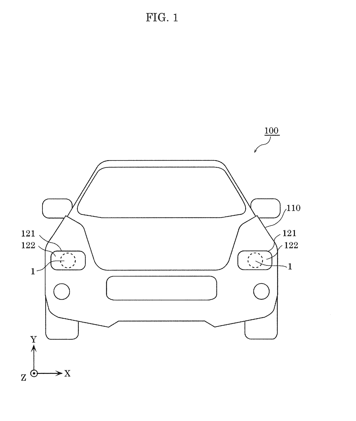
[0028]First, automobile 100 according to an embodiment will be described with reference to FIG. 1. FIG. 1 is a front view of automobile 100 according to the embodiment.

[0029]Automobile 100 according to this embodiment is one example of a vehicle, such as a four-wheeled automobile. Automobile 100 is, for example, an automobile propelled by a gasoline engine, an automobile propelled by an electric motor, or a hybrid automobile.

[0030]As illustrated in FIG. 1, automobile 100 includes lighting apparatus 1 and vehicle body 110 on which lighting apparatus 1 is installed as a headlamp. Vehicle body 110 includes two lighting apparatuses 1, one on each of the left and right sides of the front of vehicle body 110.

[0031]Housing 121 for housing lighting apparatus 1 and front cover 122 disposed in front of housing 121 are provided on vehicle body 110.

[0032]Housing 121 is, for example, a metal housing, and includes an opening through which light from lighting apparatus 1 is emitted. Fr...


PUM


Abstract

A lighting apparatus includes: a projection lens; a light source behind the projection lens; a reflector that reflects light from the light source toward the projection lens; and a shield that blocks a portion of the light reflected by the reflector to form a cutoff line in a distribution pattern of the light. A textured section demarcated by unit regions is formed on a surface of the projection lens, and when a region in a center of the projection lens is defined as a central region, and regions left and right of the central region are defined as left and right regions, respectively, in a front view, a proportion of the unit regions in the central region is greater than a proportion of the unit regions in each of the left region and the right region.

Description

CROSS REFERENCE TO RELATED APPLICATION[0001]This application claims the benefit of priority of Japanese Patent Application Number 2015-257544 filed on Dec. 28, 2015, the entire content of which is hereby incorporated by reference.BACKGROUND[0002]1. Technical Field[0003]The present disclosure relates to a lighting apparatus, an automobile including the lighting apparatus, and a projection lens.[0004]2. Description of the Related Art[0005]Vehicles such as automobiles are equipped with lighting apparatuses as headlights (headlamps) in the front. Such lighting apparatuses include a projection lens, a light source behind the projection lens, a reflector that reflects light from the light source toward the projection lens, and a shield that blocks a portion of light coming directly from the light source to form a cutoff line in a distribution pattern of the light.[0006]One conventionally known lighting apparatus of this type is a vehicle lamp capable of inhibiting an uneven distribution o...

Claims


Application Information

Patent Timeline
Patent Type & Authority Applications(United States)
IPC IPC(8): F21S8/10F21V29/76F21V29/85F21V29/503F21W107/10
CPCF21S48/1283F21S48/1109F21S48/1159F21S48/1394F21S48/14F21V29/85F21S48/1258F21S48/328F21V29/503F21V29/763F21S48/1291F21S41/25F21S41/40F21W2102/00F21W2107/10F21S41/148F21S41/19F21S41/255F21S41/275F21S41/295F21S41/321F21S41/333F21S41/43F21S45/48
Inventor KANAYAMA, YOSHIHIKOTOMODA, NAOKIHYUGA, HIDEAKI
Owner PANASONIC INTELLECTUAL PROPERTY MANAGEMENT CO LTD
Why Eureka
Try Eureka