Separator assembly

a separator and assembly technology, applied in the direction of liquid degasification, separation process, water/sewage treatment by degassing, etc., can solve the problems of serious environmental hazards, high flammability, and compound long-term negative health effects on oilfield personnel, other persons and animals, and achieve easy spotting of equipment, easy cleaning and disposal, and release a substantial amount of pressure.

Inactive Publication Date: 2015-02-24
HUGHES SPECIALTY SERVICES
View PDF13 Cites 2 Cited by
  • Summary
  • Abstract
  • Description
  • Claims
  • Application Information

AI Technical Summary

Benefits of technology

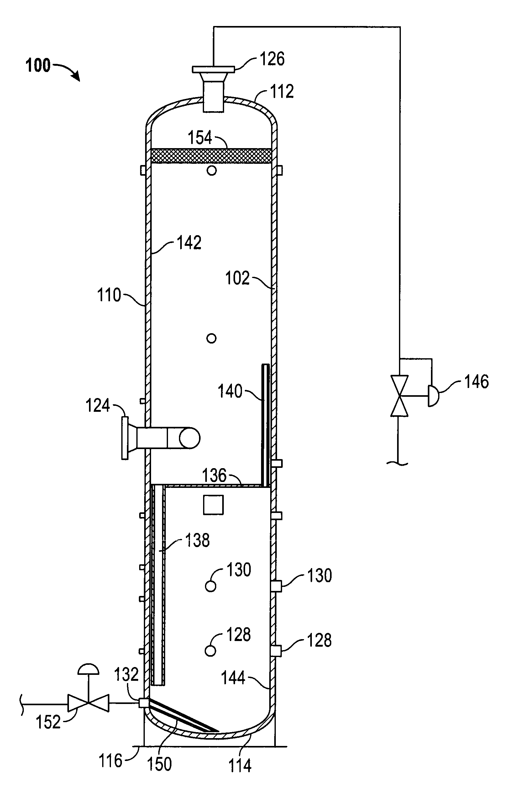
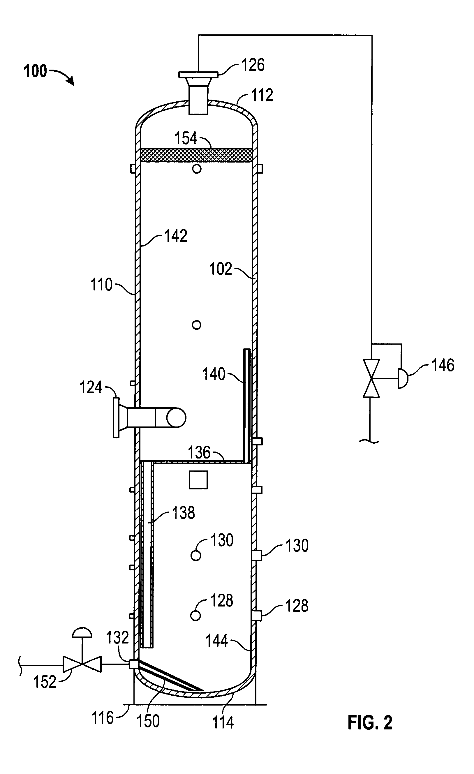
[0014]With the first stage of separation complete, all liquids and solids fall out and begin the vessel's seconds stage of separation. The fluid and sand slurry falls in a centrifugal fashion to the bottom of the vessel to as to create the separation to which the solids remain at the bottom of the vessel near a sand dump. At this point, the produced water and the crude oil begin the vessel's third and fourth stages of separation. The particular fluid separation may be maintained at desired levels in the vertical separator by dump systems with float style operators, for example. To control the emissions of harmful vapors, substantially all control operations may be carried out with compressed air rather than natural gas. The sheer capacity of the separator vessel alone may aid in the third and fourth stage separations, as the retention time of the fluid will allow the crude oil to migrate to upper level dump outlets as the water remains at lower level dump outlets inside the vessel, for example. At this point, substantially all water, oil, and sand can be dumped as desired and on a substantially consistent basis to containment areas of a customer's choice.
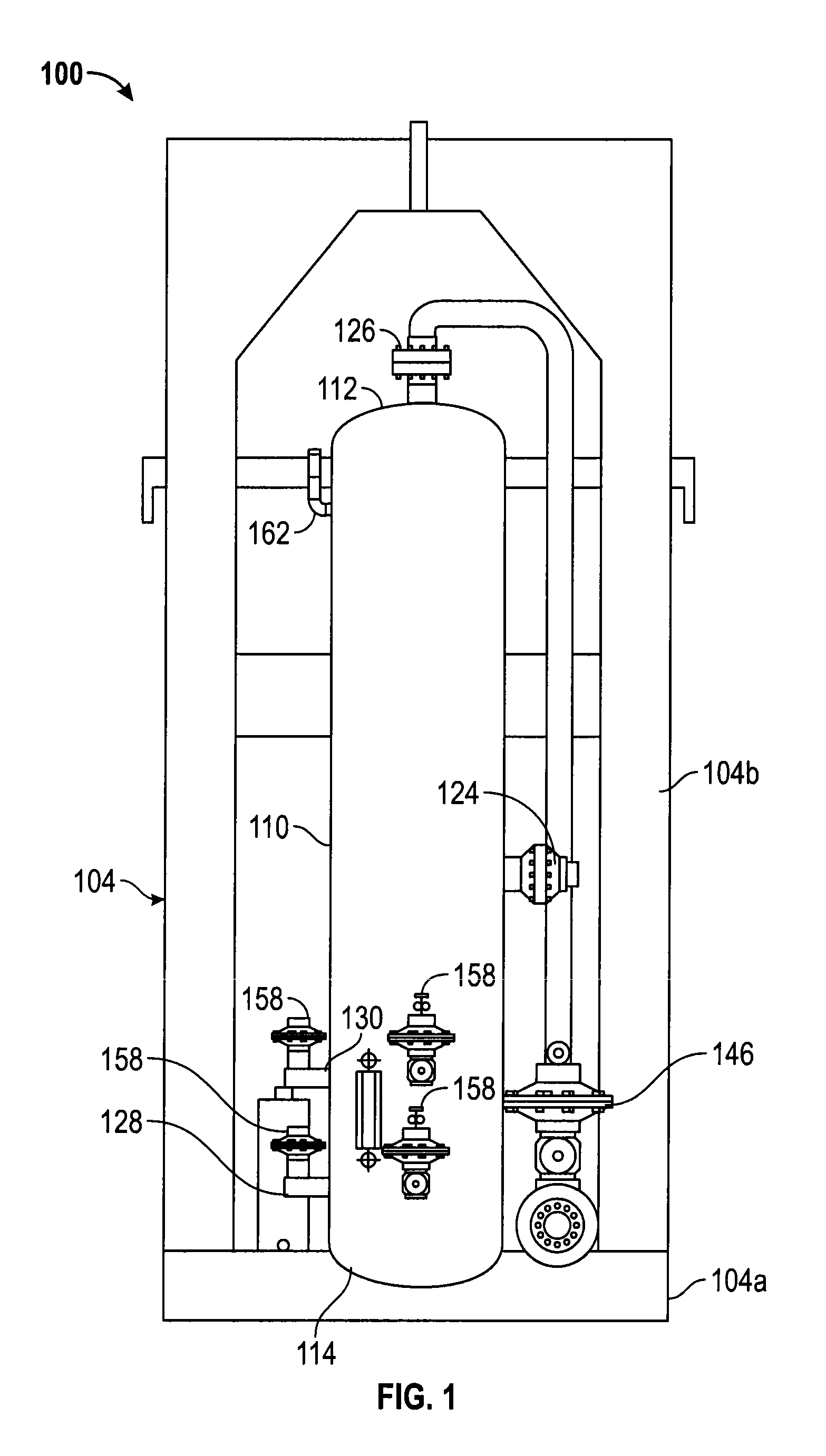
[0015]In one exemplary embodiment, the vessel may only take up an approximately an 8 feet by 8 feet square feet footprint. The vessel is a four-phase separator that will separate gas, oil, water, and sand. In one version, the vessel includes a 6 inch back pressure valve, such as a S / FMT Kimray valve, that releases pressure to a flare line and flare stack and / or tied into a meter run and sale gas line, for example. A pilot valve may sense the pressure on the vessel to open and close the backpressure valve in such a manner so as to release a substantial amount of pressure very quickly so that backpressure is not maintained on the well while in the process of drilling plugs to keep the well flowing freely. If too much backpressure is held on the well, debris may build up and the drill pipe may get stuck in the hole, for example. The vessel can handle fluid volumes up to 350 bbl per hour and handle 500 mmcf of gas per day in some exemplary embodiments of the inventive concepts disclosed herein. The inside structure of the vessel is configured to cause a swirling effect to separate the fluid from the gas. The gas also has a knock out mesh screen or mist suppressor pad, at the top of the vessel to collect any droplets of water that might be carried in the gas before it's released from the vessel. Also in this separation the sand may fall to the bottom of the vessel where it can be removed by opening a valve, for example. The sand may then be moved from the vessel to a half pit for easy cleanout and disposal. The Kimray 2200 SMT style dump valves and Wellmark controllers may remove fluid from the vessel into flowback or frac tanks for haul offs and accurate measuring, for example. This vessel may be skid-mounted and may be raised upright with a pole truck or crane for easy spotting of the equipment, for example.

Problems solved by technology

The gases dissolved in the flowback water as a result of the high pressures created during the hydraulic injection are highly flammable and pose serious environmental hazards.
VOCs are organic chemicals that have a high vapor pressure at ordinary, room-temperature conditions, and are especially problematic due to their tendency to readily dissolve in or mix with flowback water at high pressures, and to also readily evaporate from the flowback water at atmospheric pressures and ambient temperatures.
Further, most VOCs are generally not immediately toxic, but instead have compounding long-term negative health effects on oilfield personnel and other persons and animals exposed to even low concentrations of VOCs for prolonged periods of times.
There are several problems inherent in this approach, including inadequate retention times in the production separator and the flashing off of gas at the condensate and flowback atmospheric tanks resulting from the large pressure drop (e.g., from about 1400 psig to atmospheric pressure of about 15 psi).
Flash gases vented at flowback water and condensate storage tanks pose severe dangers of fires / explosions and environmental hazards of substantial amounts of HAPs emissions including VOCs.
In addition to environmental concerns, the costs associated with operating oil and gas wells are always a concern.
In the oil and gas industry, some of the initial costs to an operator begin in the construction of the location and the cost of the surface damages paid out to the owners of the surface property.
This has caused a dramatic size decrease in the oil and gas pads being built today.
If too much backpressure is held on the well, debris may build up and the drill pipe may get stuck in the hole, for example.

Method used


Image

  • Separator assembly
  • Separator assembly
  • Separator assembly

Examples


Embodiment Construction

[0022]Before explaining at least one embodiment of the inventive concepts disclosed herein in detail, it is to be understood that the inventive concepts are not limited in their application to the details of construction and the arrangement of the components or steps or methodologies set forth in the following description or illustrated in the drawings. The inventive concepts disclosed herein are capable of other embodiments or of being practiced or carried out in various ways. Also, it is to be understood that the phraseology and terminology employed herein is for the purpose of description only and should not be regarded as limiting the inventive concepts disclosed and claimed herein in any way.

[0023]In the following detailed description of embodiments of the inventive concepts, numerous specific details are set forth in order to provide a more thorough understanding of the inventive concepts. However, it will be apparent to one of ordinary skill in the art that the inventive conc...


PUM

PropertyMeasurementUnit
areaaaaaaaaaaa
pressureaaaaaaaaaa
diameteraaaaaaaaaa

Abstract

A separator assembly comprises a vertical vessel including a fluid inlet for receiving a fluid including a gas, at least two liquids, and solids, at least two liquid outlets for discharging the liquids, a gas outlet at an upper end thereof for discharging gas, and a solids outlet at a lower end thereof for discharging solids. A baffle plate extends across the vessel, and cooperates with the vessel to define an upper section and a lower section, and has a first conduit extending downwardly so that liquids and solids may flow into the lower section, and a second conduit extending upwardly so that gases may flow from the lower section to the upper section. A backpressure valve is in fluid communication with the gas outlet and is configured to discharge gas while maintaining a selected level of pressure inside the vessel.

Description

INCORPORATION BY REFERENCE[0001]The entirety of U.S. Provisional Application Ser. No. 61 / 563,349, filed on Nov. 23, 2011, is hereby expressly incorporated herein by reference.BACKGROUND[0002]1. Field of the Inventive Concepts[0003]The inventive concepts disclosed generally relate to fluid separators, and more particularly, but not by way of limitation, to four-phase vertical separators for use in oilfield operations.[0004]2. Brief Description of Related Art[0005]Shale gas production operations throughout the United States and all over the world increasingly rely on hydraulic fracturing as a completion process to stimulate natural gas production from shale formations. Hydraulic fracturing involves high-pressure injection of large quantities of water, along with sand, and other small amounts of chemical additives, into a well. The high-pressure water creates small fractures, or cracks, in the surrounding rock formation, and sand or other propant used wedges into the cracks and prevent...

Claims


Application Information

Patent Timeline
Patent Type & Authority Patents(United States)
IPC IPC(8): B01D19/00B01D17/02B01D17/12C02F1/20C02F1/40C02F101/32
CPCC02F1/20B01D17/0217B01D17/12B01D19/0052B01D19/0063C02F1/40C02F2101/32C02F2101/322C02F2201/008C02F2209/42
Inventor HUGHES, JASON L.JACKSON, SHANNON L.WRIGHT, JAMES D.
Owner HUGHES SPECIALTY SERVICES
Why Eureka
Try Eureka