
Reel-changing apparatus particularly suitable for feeding working machines

Active Publication Date: 2017-07-27
DOTTA ANGELO
View PDF1 Cites 0 Cited by
  • Summary
  • Abstract
  • Description
  • Claims
  • Application Information

AI Technical Summary

Benefits of technology

The invention is a reel-changing apparatus that allows for the efficient and quick replacement of reams of material. The apparatus includes a rotating element carrying multiple reel-holders, and support and guiding means for moving the rotating element to and from the working point. The apparatus also includes a mechanism for cutting and reconnecting the material, as well as a mechanism for feeding working machines. Additionally, the invention includes an abutment element for blocking the flow of material downstream of an exhausted reel and a mobile element for cutting and holding the material from the exhausted reel, allowing for quick replacement with a new reel. The technical effects of this invention include improved efficiency and productivity in the material cutting and processing process.

Problems solved by technology

The service time can be quite reduced by adopting two reel-holders located in the working position and to be alternated in feeding the same material; however, this may involve problems of overall dimensions as well as of safety for the operators if they have to intervene on one of the two reels for replacing it while the machine is running.

Method used


Image

  • Reel-changing apparatus particularly suitable for feeding working machines
  • Reel-changing apparatus particularly suitable for feeding working machines
  • Reel-changing apparatus particularly suitable for feeding working machines

Examples


Embodiment Construction

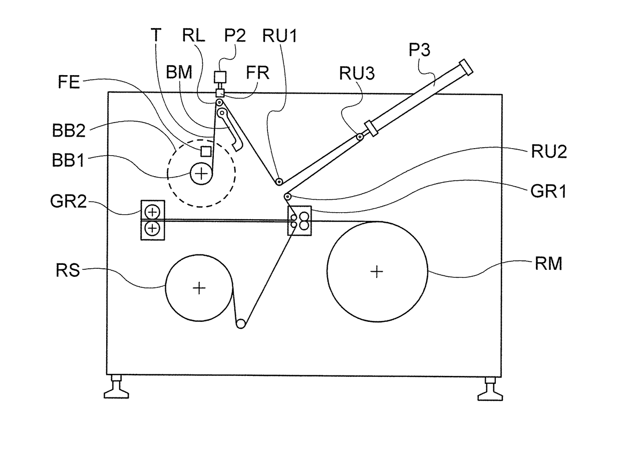
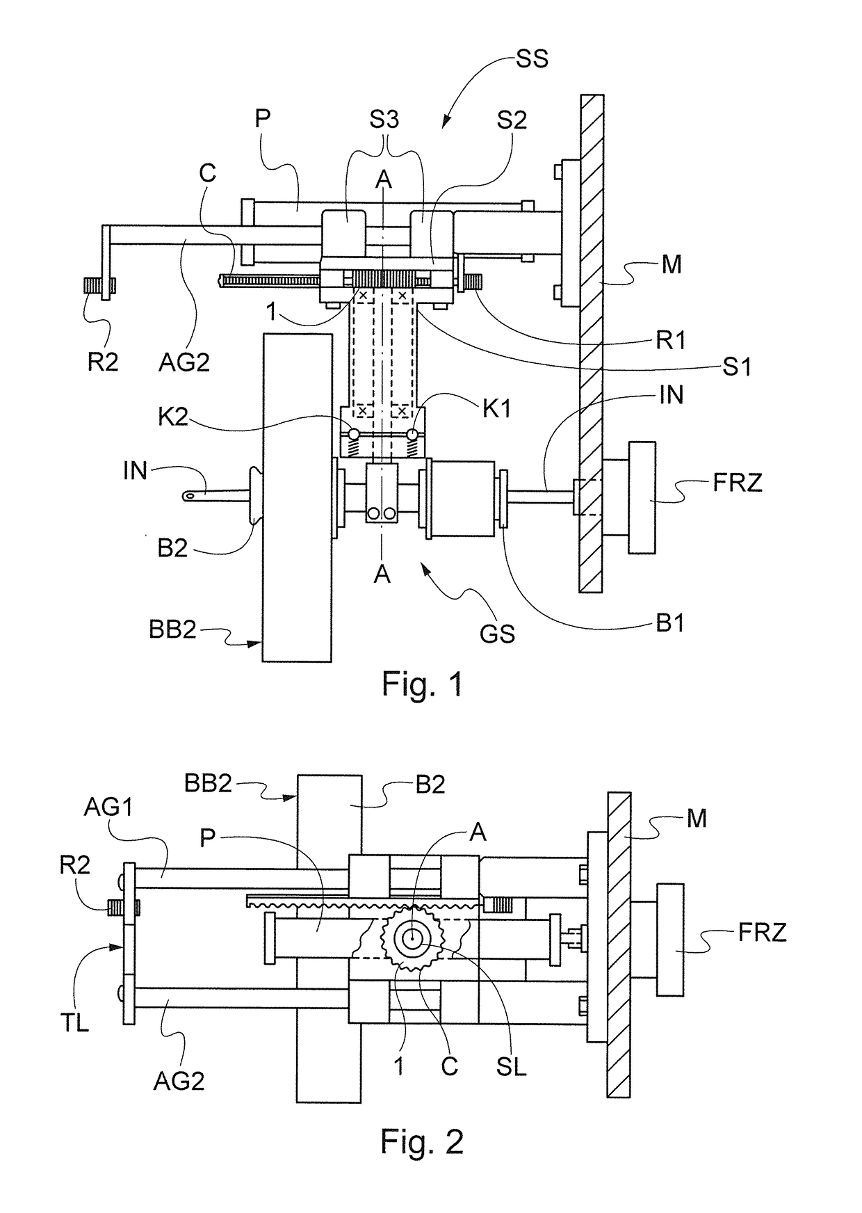
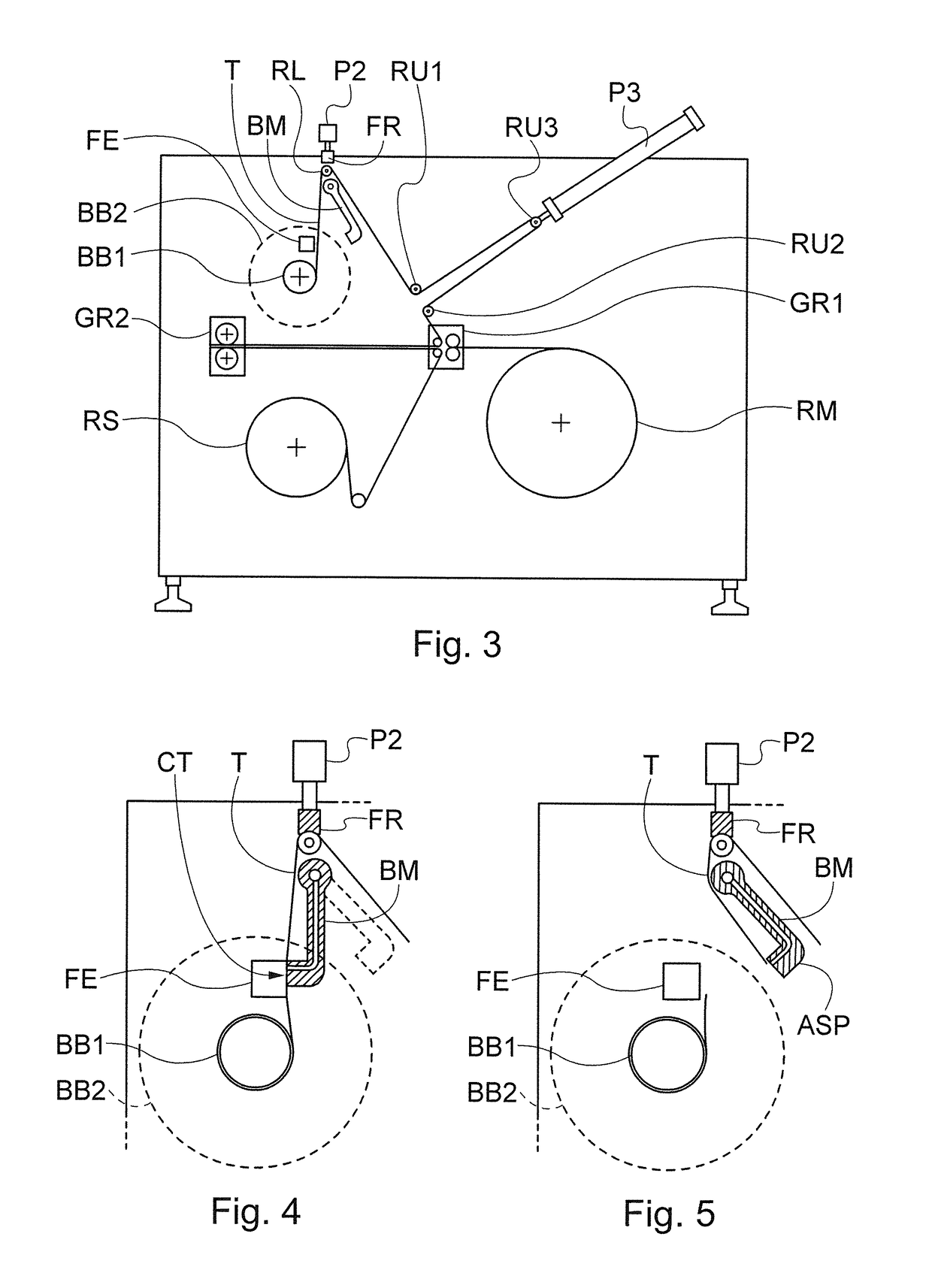
[0023]As illustrated in FIG. 1, the two opposite reel-holders B1,B2 are fixed to the rotating shaft A, thus forming a carousel GS which is supported by the composite assembly SS; said assembly comprises a flanged tubular element S1—which houses the bearings supporting the rotating shaft A—connected, by means of screws provided with spacers, to the plate S2 to which backing elements S3, which are hollow and provided inside with ball sleeves or bushes, are fixed. This composite assembly SS, defined in short as “carriage” is slidably fit onto the two guiding shafts AG1 AG2, as better visible in FIG. 2, and is controllable forward and backward (relative to the machine wall M) by means of the pneumatic piston P.

[0024]FIG. 2 (top view) also shows the toothed rack C, slidably inserted into the carriage SS, and the gear 1 which is coaxial with the shaft A and connected thereto and is in engagement with the toothed rack C; the rack can come into contact with the two abutment elements R1,R2 f...


PUM


Abstract

Apparatus suitable for guaranteeing a quick and automatic change of materials wound on reels, said apparatus consisting mainly of a reel-alternating mechanism combined with a mechanism for cutting and reconnecting the reeled material.

Description

TECHNICAL FIELD[0001]The subject-matter of the invention is a combination of mechanisms suitable for guaranteeing a quick and automatic change of materials wound on reels, with substitution of exhausted reels with fresh ones that replace the former ones and continue the work after reconnecting the reeled material.PRIOR ART[0002]Nowadays it is usual, in working machines of common use, to change reels by means of a manual operation while the machine is not running, said operation comprising cutting of the remaining material from the exhausted reel, dismounting the reel (i.e. its core), mounting a fresh reel and connecting the leading edge thereof to the remaining trailing edge of the exhausted reel; after these operations the machine can be re-started. The service time can be quite reduced by adopting two reel-holders located in the working position and to be alternated in feeding the same material; however, this may involve problems of overall dimensions as well as of safety for the ...

Claims


Application Information

Patent Timeline
IPC IPC(8): B65H19/30B65H19/26
CPCB65H19/265B65H19/30B65H16/023B65H16/04B65H19/1847B65H19/1868B65H2301/41282B65H2301/46024B65H2301/4631B65H2301/4641B65H2406/30B65H2406/351B65H2408/2412B65H2408/24153
Inventor DOTTA, ANGELO
Owner DOTTA ANGELO
Learn More