Fastening structure and fastening method

a technology of fastening structure and fastening method, which is applied in the direction of threaded fasteners, screwed fasteners, manufacturing tools, etc., can solve the problems of varying the tensile force needed to break the workpiece, workpiece deformation, and time and effort required to machine the workpiece to be attached, and achieves strong fastening force

Inactive Publication Date: 2017-08-03
NEWFREY
View PDF1 Cites 2 Cited by
  • Summary
  • Abstract
  • Description
  • Claims
  • Application Information

AI Technical Summary

Benefits of technology

[0033]If the sleeve is compressed in the center axis direction of the blind rivet, the workpiece can be held with a strong fastening force.

Problems solved by technology

Because existing blind rivets break the shaft of the mandrel at a narrow breakable portion, a fastening tool is needed, and the workpiece can undergo deformation if the load is not uniform.
However, a disadvantage of Patent Reference 1 is that it takes time and effort to machine the workpiece to be attached, since corrugations must be formed in the holes of the workpieces.
Another problem is that when a shearing-off portion is provided on the shaft-shaped component, the breaking load of the tensile force needed to break it varies greatly; that is, the fastening force is not stabilized.
However, a disadvantage of Patent Reference 2 is that time and labor are needed to form a thread hole in the connector.
However, if the standoff component of the spacer is stretched when the expanded portion passes through and is made longer in the axial direction of the shaft, a fastening force (shaft force) for compressing the workpiece in the axial direction cannot be obtained.
However, in Reference 1, a disadvantage is that the fastening force is not stabilized; that is, the fastening force varies, because the load on the mandrel is not stabilized during breaking.
A further disadvantage is that a fastening force cannot be obtained if the expansion of a component is not adequate.
In Patent Reference 2, a disadvantage is that an adequate fastening force cannot be obtained if the standoff component of the spacer is stretched.

Method used


Image

  • Fastening structure and fastening method
  • Fastening structure and fastening method
  • Fastening structure and fastening method

Examples


Embodiment Construction

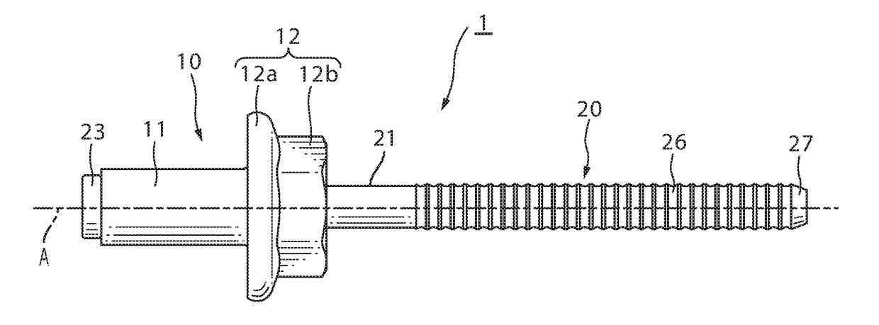
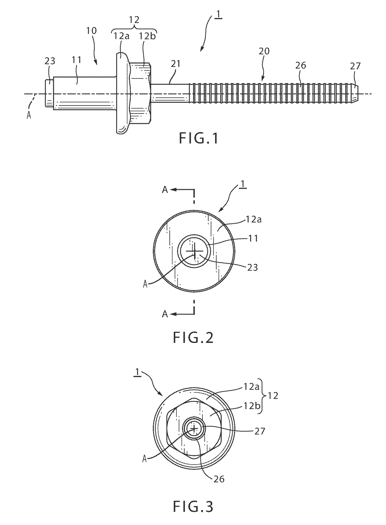
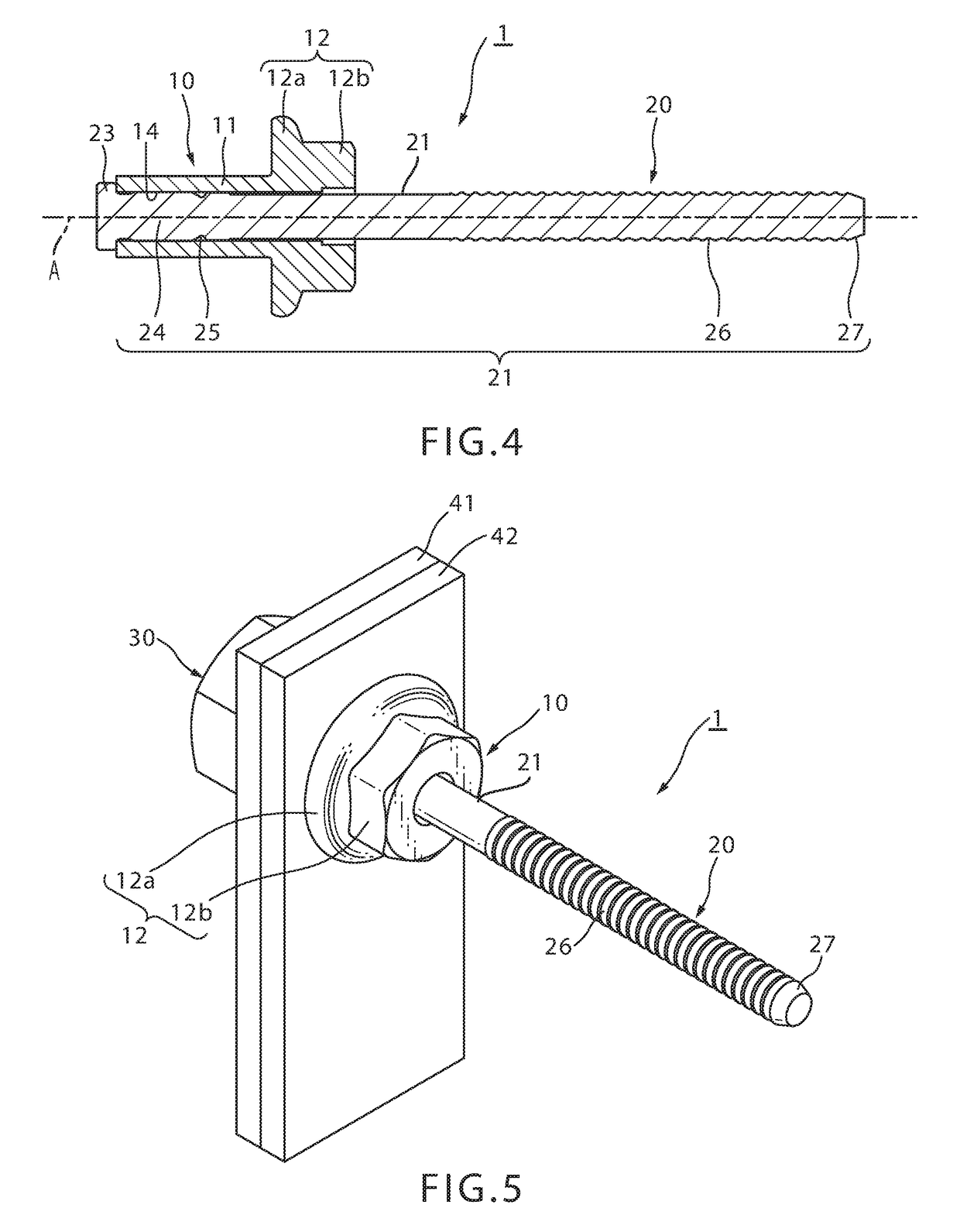
[0048]Next, a blind rivet subassembly 1 according to an embodiment of the present invention will be explained by referring to the Drawings. FIG. 1 is a front elevational view of blind rivet subassembly 1 of the present invention; FIG. 2 is a left side view; and FIG. 3 is a right side view. FIG. 4 is a cross-sectional view of the blind rivet 1 along line A-A of FIG. 2.

[0049]Blind rivet subassembly 1 is provided with a rivet body 10 and a mandrel 20.

[0050]Rivet body 10 includes a hollow tubular sleeve 11 and a rivet head 12 which is formed on one end of sleeve 11, having a larger diameter than sleeve 11. Rivet head 12 has a flange 12a and a polygonal portion 12b which is contiguous to flange 12a, and is formed on an end of the rivet body on the opposite side of the flange from the sleeve.

[0051]The outer diameter of flange 12a is larger than the outer diameter of sleeve 11 so that it abuts the surface of a workpiece 42 over a wide area (FIG. 5). Polygonal portion 12b is formed on the e...


PUM

PropertyMeasurementUnit
pulling forceaaaaaaaaaa
forceaaaaaaaaaa
forceaaaaaaaaaa

Abstract

A fastening structure includes a blind rivet and a nut. The blind rivet includes a rivet body having a hollow sleeve, a rivet head at the end of the sleeve and a through-hole; and a mandrel having an elongated stem and a mandrel head. The nut is positioned around the sleeve side end of the rivet body and the mandrel head and abuts one of the workpieces. The end portion of the sleeve is enlarged by the mandrel head and is embedded in the internal screw threads of the nut. The workpieces are thus fastened between the nut and the rivet head.

Description

CROSS-REFERENCE TO RELATED APPLICATIONS[0001]This application is a continuation of PCT Application No. PCT / JP2015 / 75431, filed on Sep. 8, 2015 which claims priority from Japanese Patent Application No. 2014-222595, filed on Oct. 31, 2014, the entire disclosure of which is incorporated herein by reference.BACKGROUND OF THE PRESENT INVENTION[0002]The present invention pertains to a fastening structure. In particular, it pertains to a fastening structure and a fastening method which includes a blind rivet that can fasten with a stabilized fastening force.[0003]Blind rivets provided with a hollow metal rivet body including a sleeve and a rivet head on one end of the sleeve, and a metal mandrel with a shaft that extends through and projects out from a through-hole in the rivet body, are well-known. Blind rivets have the advantage that multiple workpieces can be joined working from one side only.[0004]The rivet body of a blind rivet has a rivet head formed on one end; a tubular hollow sle...

Claims


Application Information

Patent Timeline
Patent Type & Authority Applications(United States)
IPC IPC(8): F16B19/10F16B37/00B21J15/04F16B5/04
CPCF16B19/1054B21J15/043F16B37/00F16B5/04B23P19/062F16B37/064
Inventor TAKEDA, ATSUSHISAKODA, KANJIYAMADA, TOMOYOSHI
Owner NEWFREY
Why Eureka
Try Eureka