

Power amplifier circuit
a power amplifier and circuit technology, applied in the direction of rf amplifiers, dc-amplifiers with dc-coupled stages, amplifiers with semiconductor devices/discharge tubes, etc., can solve the problems of increasing radio frequency shortage, configuration disclosed in the above non-patent literature is not sufficient to enhance the q factor in a frequency band over 100 ghz, etc., to enhance the q factor and enhance the power gain
- Summary
- Abstract
- Description
- Claims
- Application Information
AI Technical Summary
Benefits of technology
Problems solved by technology
Method used
Image

Examples
first embodiment
[Configuration of Power Amplifier Circuit]
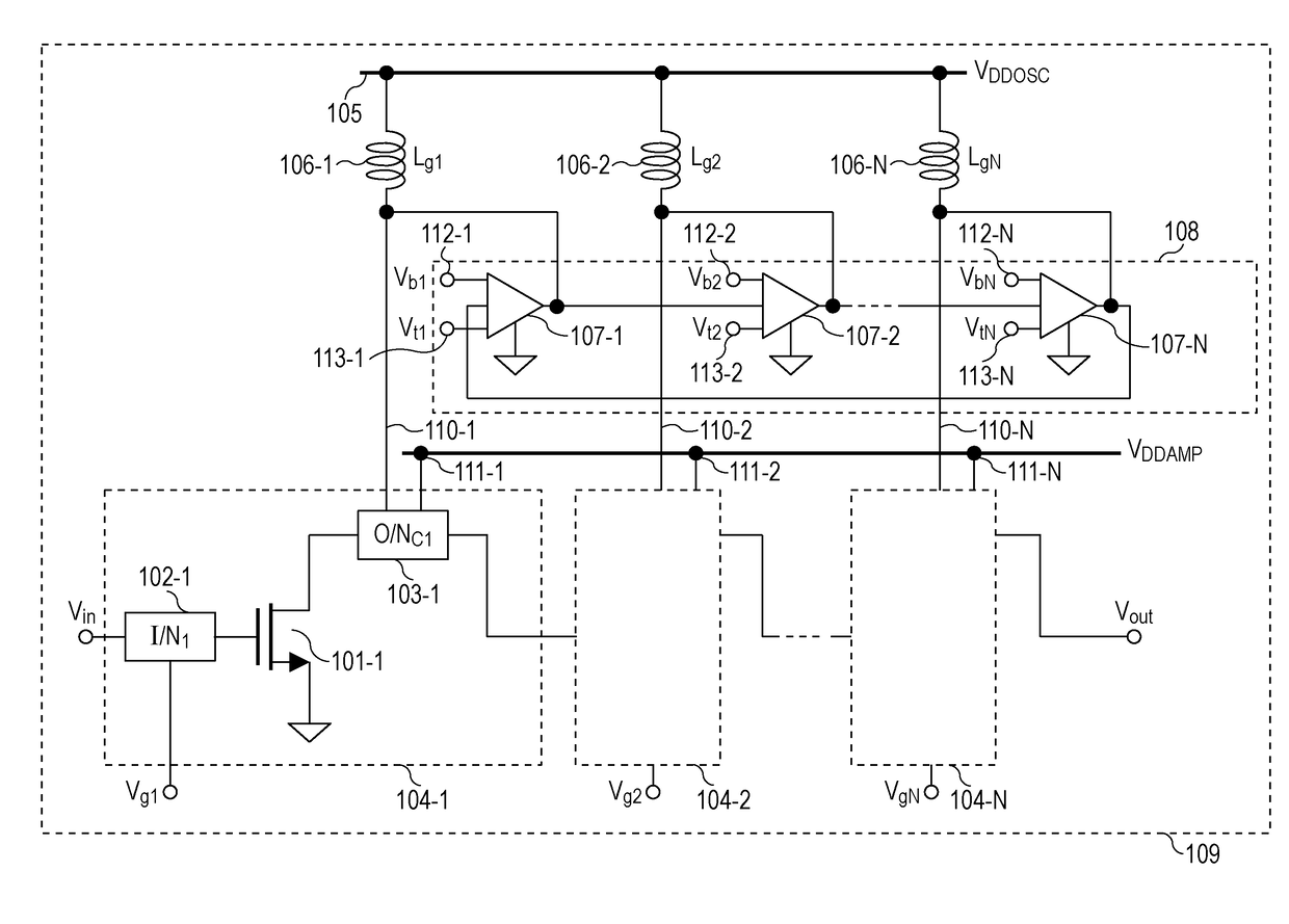
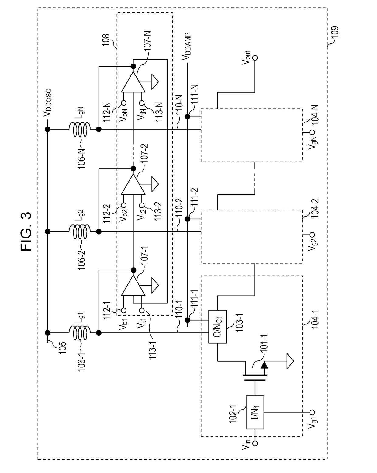
[0032]FIG. 3 is a diagram illustrating a configuration example of a power amplifier circuit 109 according to a first embodiment. The power amplifier circuit 109 illustrated in FIG. 3 includes N (N is an integer equal to or greater than 2) power amplifier circuit cores 104-1 to 104-N, a ring-oscillator-type gm generation circuit 108, and N inductors 106-1 to 106-N.
[0033]The power amplifier circuit core 104-1 amplifies the power of an input signal Vin. To be more specific, the power amplifier circuit core 104-1 includes an input transistor 101-1, an input circuit 102-1 connected to an input terminal of the input transistor 101-1, and an output circuit core 103-1 connected to an output terminal of the input transistor 101-1.
[0034]Configurations of the other power amplifier circuit cores 104-2 to 104-N (not illustrated) are the same as the configuration of the power amplifier circuit core 104-1.
[0035]In the embodiment, the N power amplifier circ...
second embodiment
[0064]FIG. 10 is a diagram illustrating a configuration example of a power amplifier circuit according to a second embodiment. In FIG. 10, note that the configuration same as that of the first embodiment (FIG. 3) is denoted by the same reference sign in FIG. 3, and its description is omitted.
[0065]In FIG. 10, to simplify the diagram, a configuration including the gm generation circuit core 107-1 and the terminals 112-1 and 113-1 in the ring-oscillator-type gm generation circuit 108 is denoted by a configuration 114-1. Likewise, configurations at second and following stages are denoted by configurations 114-2 to 114-N.
[0066]The configuration of the power amplifier circuit 109 according to the first embodiment (FIG. 3) includes the N power amplifier circuit cores 104-1 to 104-N which are cascade-connected. On the other hand, in the configuration of FIG. 10, X (X is an integer equal to or greater than 1 but less than N) of the N power amplifier circuit cores 104-1 to 104-N are connecte...
third embodiment
[0074]A calibration method for the power amplifier circuit is described in a third embodiment.
[0075]FIG. 11 is a diagram illustrating a configuration example of a power amplifier circuit according to the third embodiment. In FIG. 11, note that the configuration same as that of the first embodiment (FIG. 3) or the second embodiment (FIG. 10) is denoted by the same reference sign in FIGS. 3 and 10, and its description is omitted.
[0076]In FIG. 11, a configuration of a power amplifier circuit 909 is the configuration in the first embodiment (FIG. 3) with a phase locked loop (PLL) 914, a lock detector (LD) circuit 915, and a power detector (PD) circuit 918 added thereto. Otherwise, the power amplifier circuit 909 may have the configuration (not illustrated) in the second embodiment (FIG. 10) with the PLL 914, the LD circuit 915, and the PD circuit 918 added thereto.
[0077]The PLL 914 receives, as input, output from the ring-oscillator-type gm generation circuit 108, a reference signal Vre...
PUM
 Abstract
Description
Claims
Application Information