
Apparatus and method for localizing defect location and apparatus and method for identifying cause of defect in optical transport network (OTN) based on tandem connection monitoring (TCM) coordinates and defect traceback

a technology of optical transport network and defect location, applied in the field of apparatus and method for localizing defect location and apparatus and method for identifying cause of defect in optical transport network (otn) based, can solve the problems of difficulty in interrupting a service in the otn, difficulty in identifying the root cause of such defect, and propagation of defects to a path layer. achieve the effect of faster and more accurate manner

Inactive Publication Date: 2017-08-03
ELECTRONICS & TELECOMM RES INST
View PDF2 Cites 0 Cited by
  • Summary
  • Abstract
  • Description
  • Claims
  • Application Information

AI Technical Summary

Benefits of technology

The patent provides a method to quickly and accurately identify the root cause and location of a defect in an optical transport network (OTN). This is done by using a combination of localized defect monitoring and an algorithm that traces back the cause of the defect in the opposite direction. This approach improves the efficiency and accuracy of identifying defects in OTNs.

Problems solved by technology

In particular, in an OTM layer structure in which a number of optical data units (ODUs) having relatively small volumes are multiplexed to an ODU having a relatively large volume, a defect may be propagated to a path layer from a section layer even when the defect has a single cause.
Thus, it may be difficult to identify the root cause of such defect because there may be other defects as well.
The related art using the loopback technology may have difficulty interrupting a service in the OTN while a loopback process is running.
Here, the alarm suppression technology using the AIS may only report an alarm that is generated on a relatively high layer having a large volume to the NMS, and may not report an alarm generated on a relatively low layer having a small volume by suppressing the alarm based on the AIS.
However, when defects concurrently occur, due to another cause, on a layer lower than a layer on which the alarm is generated, the alarm suppression technology using the AIS may have difficulty because the alarm generated on the lower layer due to another cause is not reported until the alarm generated on the higher layer has been cleared.

Method used


Image

  • Apparatus and method for localizing defect location and apparatus and method for identifying cause of defect in optical transport network (OTN) based on tandem connection monitoring (TCM) coordinates and defect traceback
  • Apparatus and method for localizing defect location and apparatus and method for identifying cause of defect in optical transport network (OTN) based on tandem connection monitoring (TCM) coordinates and defect traceback
  • Apparatus and method for localizing defect location and apparatus and method for identifying cause of defect in optical transport network (OTN) based on tandem connection monitoring (TCM) coordinates and defect traceback

Examples


Embodiment Construction

[0034]Hereinafter, some example embodiments will be described in detail with reference to the accompanying drawings. Regarding the reference numerals assigned to the elements in the drawings, it should be noted that the same elements will be designated by the same reference numerals, wherever possible, even though they are shown in different drawings. Also, in the description of embodiments, detailed description of well-known related structures or functions will be omitted when it is deemed that such description will cause ambiguous interpretation of the present disclosure.

[0035]It should be understood, however, that there is no intent to limit this disclosure to the particular example embodiments disclosed. On the contrary, example embodiments are to cover all modifications, equivalents, and alternatives falling within the scope of the example embodiments. Like numbers refer to like elements throughout the description of the figures.

[0036]In addition, terms such as first, second, A...


PUM


Abstract

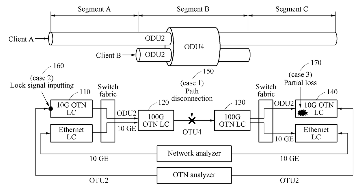
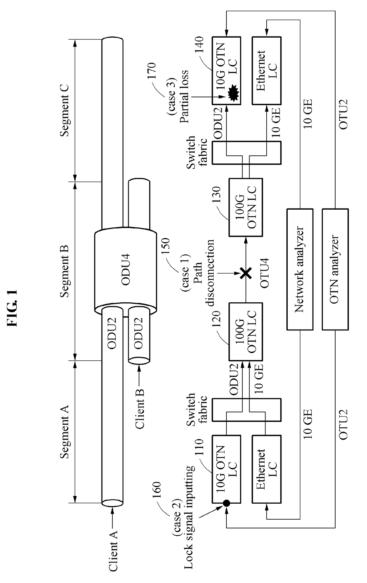
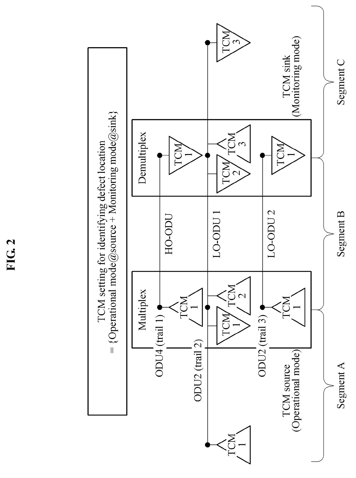
A method of localizing a defect location and a method of identifying a cause of a defect in an optical transport network (OTN). The method of localizing a defect location in an OTN includes generating tandem connection monitoring (TCM) coordinates consisting of a TCM level and trail information of an optical data unit (ODU) based on a relationship between an OTN line card (LC) and the ODU in the OTN, localizing the defect location in the OTN by converting the TCM level to a segment on the TCM coordinates, and identifying a root cause using a defect identification algorithm that traces back the cause of the defect in an opposite direction to that in which the defect is propagated based on an OTN layer structure.

Description

CROSS-REFERENCE TO RELATED APPLICATION(S)[0001]This application claims the priority benefit of Korean Patent Application No. 10-2016-0011611, filed on Jan. 29, 2016, in the Korean Intellectual Property Office, the disclosure of which is incorporated herein by reference for all purposes.BACKGROUND[0002]1. Field[0003]One or more example embodiments relate to a method of localizing a defect and a method of identifying a cause of a defect in an optical transport network (OTN) by tracing back the defect based on tandem connection monitoring (TCM) coordinates, and more particularly, to a method of localizing a defect location in an OTN based on TCM coordinates consisting of a TCM level and trail information of an optical data unit (ODU) and identifying a cause of the defect in the OTN by tracing back information on the defect occurring in the localized defect location in an opposite direction to that in which the defect is propagated based on OTN layer structure.[0004]2. Description of Re...

Claims


Application Information

Patent Timeline
IPC IPC(8): H04B10/079H04J14/02
CPCH04B10/0791H04J14/0227H04J2203/0051H04B10/27H04J3/14H04J2203/006
Inventor LEE, WON KYOUNGKIM, HO GEONRYOO, JEONG-DONGCHEUNG, TAESIKJOO, BHEOM SOON
Owner ELECTRONICS & TELECOMM RES INST
Learn More