Shock detector circuit and method for operation thereof

a detector circuit and detector technology, applied in the direction of instruments, apparatus for force/torque/work measurement, dynamo-electric converter control, etc., can solve the problems of affecting the operation of the motor, the time indication provided by the hands is likely to no longer be accurate, and the motor located inside the watch is subject to shock, etc., to achieve a faster and more accurate manner.

Active Publication Date: 2018-11-27
ETA SA MFG HORLOGERE SUISSE
View PDF12 Cites 0 Cited by
  • Summary
  • Abstract
  • Description
  • Claims
  • Application Information

AI Technical Summary

Benefits of technology

[0009]It is an object of the invention to overcome the drawbacks of the prior art by proposing to provide a shock detector device for a motor allowing the detection of a shock in a faster and more accurate manner.

Problems solved by technology

These motors, located inside the watch, are subjected to shocks which may be caused by the watch being dropped or by a violent movement of the user.
These shocks are then likely to disrupt the operation of the motors.
These disruptions consist of an uncontrolled movement of the rotor or rotors whereby their inertia causes the skipping of at least one step.
Consequently, the time indications provided by the hands are likely to no longer be accurate.

Method used


Image

  • Shock detector circuit and method for operation thereof
  • Shock detector circuit and method for operation thereof
  • Shock detector circuit and method for operation thereof

Examples


Embodiment Construction

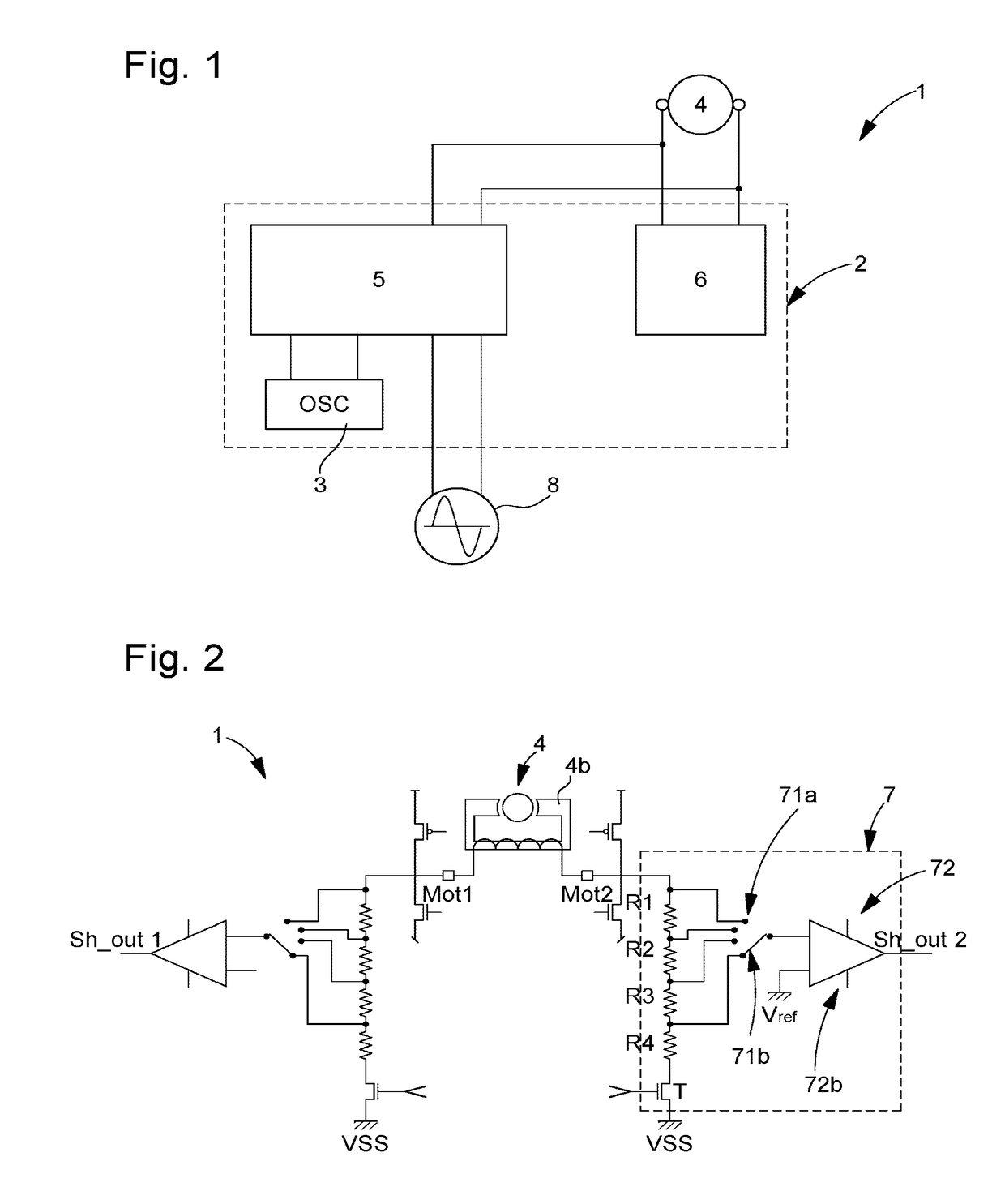
[0026]The present invention proceeds from the general idea of providing a shock detector device for a motor allowing the detection of a shock in a faster and more accurate manner.

[0027]FIG. 1 represents a schematic view of an electronic movement. This movement or electronic device 1 comprises a control module 2 clocked by a quartz oscillator system 3. For the display of time indications, such as the hour and second, hands are mounted on motors 4 to be driven in rotation. The motors used are Lavet motors, also called stepping motors, and comprise two connection terminals Mot1 and Mot2. In these motors, a magnetically charged rotor 4a of cylindrical shape creates a radial magnetic field in the air gap of a magnetic circuit 4b, on which is wound a coil whose terminals are connected to the control module, generally an integrated circuit, supplying current pulses in order to the terminals, each pulse causing the rotor to advance one step. The coil is formed by a very fine wire, wound on ...


PUM


Abstract

The present invention concerns an electronic device comprising a calculation unit capable of generating a signal representative of a physical magnitude, for a motor driving a display device, said motor comprising a rotor in a magnetic circuit, two terminals, one positive and one negative, via which the calculation unit controls the motor, the electronic device further comprising at least one shock detector circuit connected between the calculation unit and a motor terminal for the detection of an external shock applied to the motor,said motor having a first position of stable equilibrium placed at a reference angular position and a second position of stable equilibrium placed at 180° from the first stable angular position, for each direction of rotation, a maximum angular position from which it is no longer possible to return the motor rotor into a prior angular position,the calculation unit using an algorithm which, following a shock, can detect the direction of rotation of the rotor by analyzing an induced voltage detected by said detector circuit and cause to be sent a blocking pulse of reverse polarity to that of the induced voltage.

Description

[0001]This application claims priority from European Patent Application No 15195209.0 of Nov. 18, 2015, the entire disclosure of which is hereby incorporated herein by reference.[0002]The present invention concerns an electronic device comprising a calculation unit capable of generating a signal representative of a physical magnitude, for a motor driving a display device, said motor comprising two terminals, one positive and one negative, via which the calculation unit controls the motor, the electronic device further comprising at least one shock detector circuit connected between the calculation unit and the motor terminals for the detection of an external shock applied to the motor.BACKGROUND OF THE INVENTION[0003]There are known timepieces comprising a case inside which an electromechanical timepiece movement is arranged. Such a movement is clocked by a quartz oscillator system. For the display of time indications, such as the hour and second, hands are mounted on motors to be d...

Claims


Application Information

Patent Timeline
Patent Type & Authority Patents(United States)
IPC IPC(8): H02P8/02G01P15/08G04C3/14
CPCH02P8/02G04C3/143G01P15/0802H02P6/185G01L5/00G04C3/14H02P29/02
Inventor KLOPFENSTEIN, FRANCOISBERTHOUD, JOERGJEANNET, NICOLASGODAT, YVESBONNET, THIERRY
Owner ETA SA MFG HORLOGERE SUISSE
Why Eureka
Try Eureka