Downlight

a technology of downlight and recessed lamps, which is applied in the direction of lighting device details, lighting support devices, lighting and heating apparatus, etc., can solve the problems that the height of the fixture cannot exceed the width of the frame, and the removal of the light fixture in this case requires a lot of effort and strength

Active Publication Date: 2017-08-10
ZUMTOBEL LIGHTING GMBH & CO KG
View PDF1 Cites 1 Cited by
  • Summary
  • Abstract
  • Description
  • Claims
  • Application Information

AI Technical Summary

Benefits of technology

[0013]The mounting frame designed in accordance with the invention can be used to accommodate a single light fixture. Or, as specified above, the solution according to the invention also provides the possibility of disposing numerous light fixtures having a similar design on a common mounting frame in a simple manner.

Problems solved by technology

None of these various variations, however, have proven to be optimal, because, e.g., with the first variation, in which a twisted insertion and subsequent locking in place is provided, the light fixture together with the recessed lamp cannot exceed the width of the frame with regard to its height.
A removal of the light fixture in this case necessarily requires a lot of effort and strength, wherein the same also applies with the use of corresponding spring mechanisms, because in this case, the springs must be designed such that they are strong enough to retain the light fixture with the additional luminaire head.
Furthermore, in this case a relatively large gap is necessary in order to enable removal, potentially using tools.
This leads in turn to the possibility that unattractive gaps may result with so-called channel solutions, in which numerous light fixtures are disposed adjacently to one another in a mounting frame.

Method used


Image

  • Downlight
  • Downlight
  • Downlight

Examples


Embodiment Construction

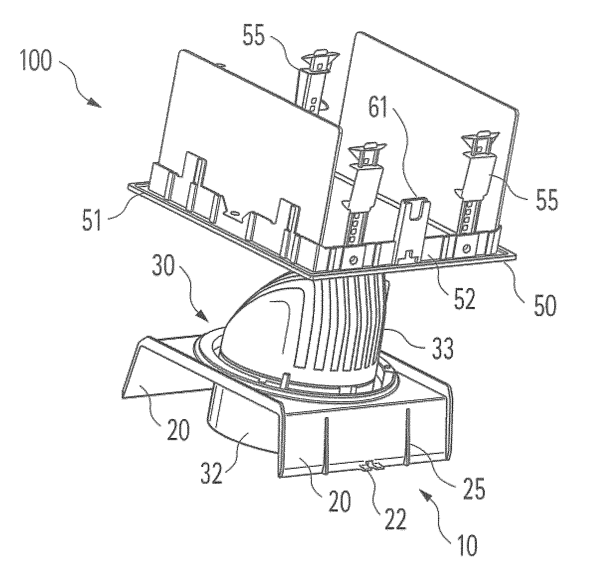
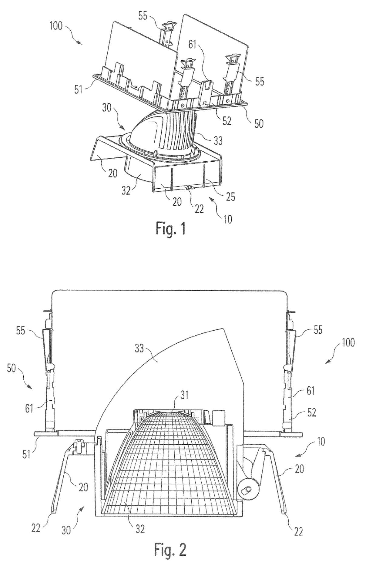
[0025]FIGS. 1 and 2 first show, in two different perspectives, the main components of a downlight designed according to the invention, provided as a whole with the reference symbol 100. As described in the introduction, this downlight 100 is designed to be installed in a mounting hole—square in this case, and not shown—of a suspended ceiling. Light is then projected downward onto a region that is to be illuminated. Downlights of this type have many uses, both for lighting work spaces as well as in spaces of public buildings, e.g. museums and the like.

[0026]The attachment of such downlights to a ceiling construction is normally such that initially a first element is joined permanently and securely to the ceiling such that all of the other components can be releasably installed on this first attached element. A so-called installation frame or mounting frame 50 is the element permanently joined to the ceiling, which is adapted to the mounting hole in the ceiling with regard to its shap...


PUM


Abstract

Disclosed is a downlight (100) comprising a mounting frame (50) to be mounted in the area of a ceiling mounting hole, and a light fixture (10) that is to be fastened to the mounting frame (50) and includes a luminaire head (30). The light fixture (10) is formed by a substantially C-shaped element having a main surface (11) and two angled wings (20) on two opposite sides of the main surface (11); the wings (20) of the light fixture (10) are designed in a flexible manner and in such a way as to interlock with the mounting frame (50).

Description

CROSS REFERENCE TO RELATED APPLICATION[0001]The present application is the U.S. national stage application of International Application PCT / EP2015 / 074336, filed Oct. 21, 2015, which international application was published on Apr. 28, 2016 as International Publication WO 2016 / 062754 A1. The International Application claims priority of German Patent Application 20 2014 105 019.1, filed Oct. 21, 2014.FIELD OF THE INVENTION[0002]The present invention relates to a downlight having a mounting frame to be mounted in the region of a ceiling mounting hole, and a light fixture to be attached to the mounting frame, having a luminaire head located thereon. In particular, the invention relates to a downlight with which the light fixture can be attached in a simple manner, without tools, to the mounting frameBACKGROUND OF THE INVENTION[0003]Lamps that are provided for attachment to a ceiling of a room that is to be illuminated and which are designed to project light substantially downward are nor...

Claims


Application Information

Patent Timeline
Patent Type & Authority Applications(United States)
IPC IPC(8): F21V21/04F21V17/16F21S8/02
CPCF21V21/047F21V17/164F21S8/026F21V21/045
Inventor HILDEBRAND, BENJAMIN
Owner ZUMTOBEL LIGHTING GMBH & CO KG
Why Eureka
Try Eureka