Heat exchanger ventilator
a ventilator and heat exchange technology, applied in the field of heat exchanger ventilators, can solve the problems of interruption of ventilation for supplying and exhausting air, and achieve the effects of reducing humidity, preventing moisture from freezing, and increasing exchange efficiency
- Summary
- Abstract
- Description
- Claims
- Application Information
AI Technical Summary
Benefits of technology
Problems solved by technology
Method used
Image

Examples
first exemplary embodiment
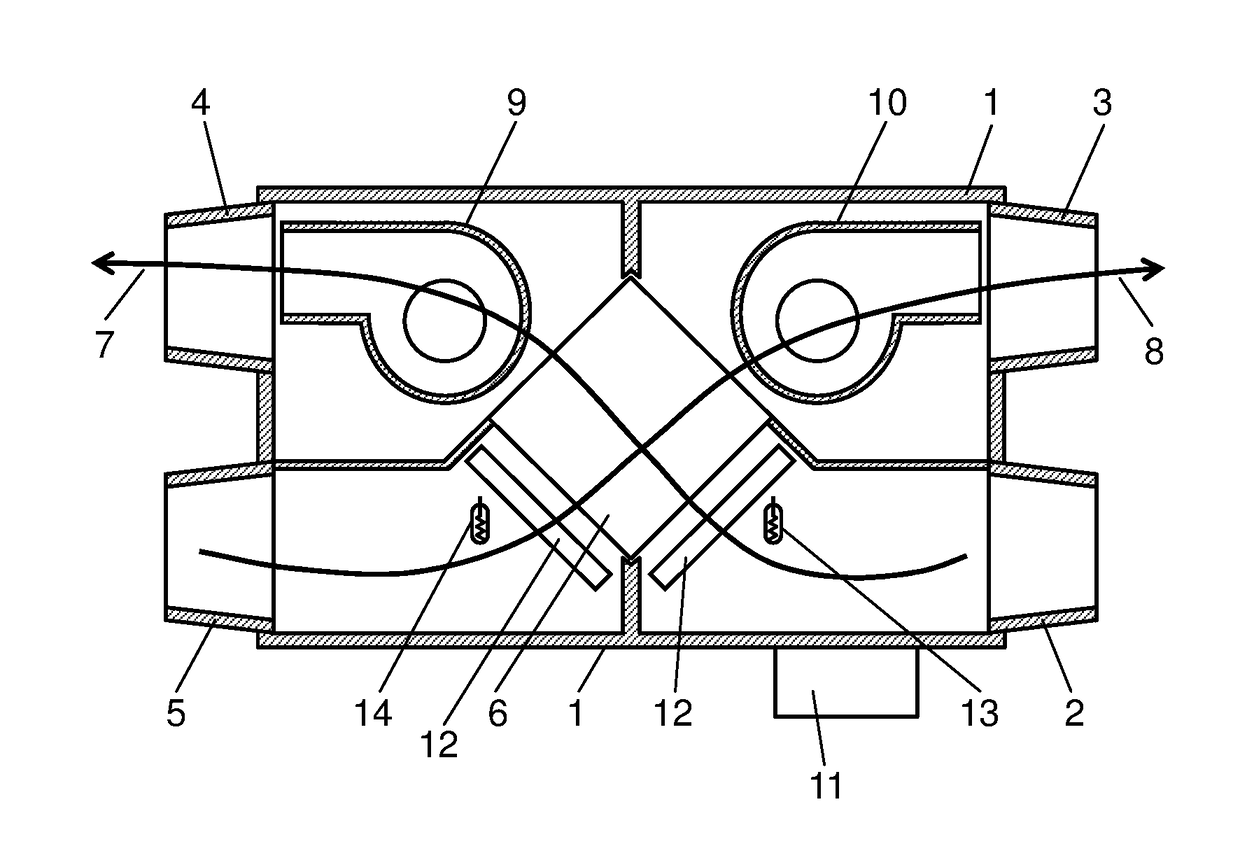
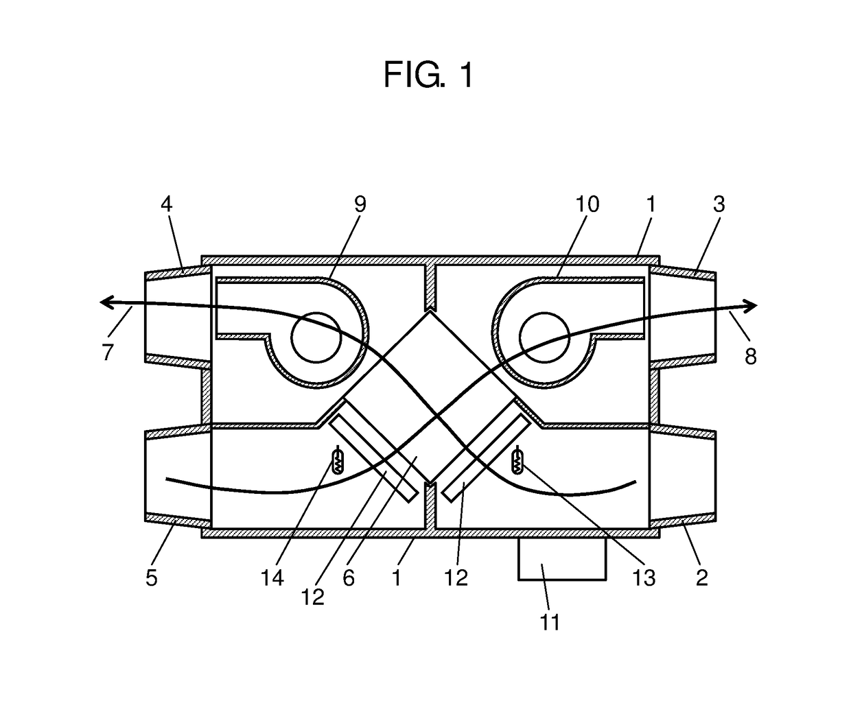
[0019]A heat exchanger ventilator according to a first exemplary embodiment of the present invention will be described with reference to FIG. 1. As shown in FIG. 1, in heat exchanger ventilator 1, outdoor air suction port 2 and indoor air exhaust port 3 are provided on a side surface of a box-shaped body, while outdoor air supply port 4 and indoor air suction port 5 are provided on another side surface opposite to the side surface.
[0020]On interior or exterior of heat exchanger ventilator 1, controller 11 is provided for controlling speed of an air supply motor of air supply fan 9 and an air exhaust motor of air exhaust fan 10.
[0021]In addition, heat exchanger ventilator 1 includes supply air conduit 7 along which fresh outdoor air (supply air) enters from outdoor air suction port 2 on the side surface, passes through heat exchange element 6 disposed inside heat exchanger ventilator 1, and flows into indoors from outdoor air supply port 4.
[0022]Furthermore, heat exchanger ventilator...
second exemplary embodiment
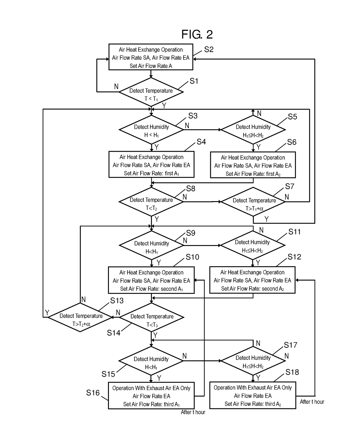
[0060]FIG. 3 is a flowchart illustrating a flow of control performed by controller 11, with respect to a heat exchanger ventilator according to a second exemplary embodiment of the present invention.
[0061]A major difference between FIG. 3 and FIG. 2 is the number of predetermined humidity ranges. That is, although FIG. 2 includes two predetermined humidity ranges: the first predetermined humidity range (H1) and the second predetermined humidity range (H1≦H2), FIG. 3 includes three predetermined humidity ranges: a first predetermined humidity range (H1), a second predetermined humidity range (H1≦H2), and a third predetermined humidity range (H2≦H3). A maximum value of the second predetermined humidity range
[0062]The control will be described one by one.
[0063]When temperature T detected by temperature detection unit 13 is equal to or above the first predetermined temperature T1 (for example, 5° C.), a supply air f...
third exemplary embodiment
[0081]A heat exchanger ventilator according to the third exemplary embodiment of the present invention will now be described with reference to FIG. 4. Components identical to components of the first exemplary embodiment are applied with identical numbers or symbols to omit duplicated descriptions.
[0082]As shown in FIG. 4, in heat exchanger ventilator 1, outdoor air suction port 2 and indoor air exhaust port 3 are provided on a side surface of a box-shaped body, while outdoor air supply port 4 and indoor air suction port 5 are provided on another side surface opposite to the side surface.
[0083]On interior or exterior of heat exchanger ventilator 1, controller 11 is provided for controlling speed of an air supply motor of air supply fan 9 and an air exhaust motor of air exhaust fan 10.
[0084]In addition, heat exchanger ventilator 1 includes supply air conduit 7 along which fresh outdoor air (supply air) enters from outdoor air suction port 2 on the side surface, passes through heat exc...
PUM
 Abstract
Description
Claims
Application Information
 - R&D
- Intellectual Property
- Life Sciences
- Materials
- Tech Scout
- Unparalleled Data Quality
- Higher Quality Content
- 60% Fewer Hallucinations
Browse by: Latest US Patents, China's latest patents, Technical Efficacy Thesaurus, Application Domain, Technology Topic, Popular Technical Reports.
© 2025 PatSnap. All rights reserved.Legal|Privacy policy|Modern Slavery Act Transparency Statement|Sitemap|About US| Contact US: help@patsnap.com