ESD protection device and manufacturing method for same

a technology of esd protection device and manufacturing method, which is applied in the direction of overvoltage arrestors using spark gaps, spark plugs, electrical apparatus, etc., can solve problems such as disassembly and assembly difficulties, and achieve the effects of improving esd protection characteristics, reducing the starting voltage, and facilitating different types of devices

Active Publication Date: 2017-08-24
MURATA MFG CO LTD
View PDF3 Cites 5 Cited by
  • Summary
  • Abstract
  • Description
  • Claims
  • Application Information

AI Technical Summary

Benefits of technology

The present invention provides an ESD protection device with significantly reduced discharge start voltage and improved ESD protection characteristics. By designing the device with a space between the first and second discharge electrodes that is smaller than the space between the second and third discharge electrodes, a non-uniform electric field is created, leading to a higher degree of concentration of electric field in the first space and a higher likelihood of partial discharge. Partial discharge occurs at a lower voltage, resulting in a lower start voltage of the disruptive discharge between the first and second discharge electrodes. The device also includes a third multilayer body formed by placing one of the first and second multilayer bodies above each other, which makes it easy to adjust the space on the sides of the first and second discharge electrodes. Overall, the device and method improve ESD protection performance by reducing discharge start voltage and improving ESD protection characteristics.

Problems solved by technology

Hence, an electron avalanche is generated successively starting from the partial discharge, thus causing disruptive discharge.

Method used


Image

  • ESD protection device and manufacturing method for same
  • ESD protection device and manufacturing method for same
  • ESD protection device and manufacturing method for same

Examples


first preferred embodiment

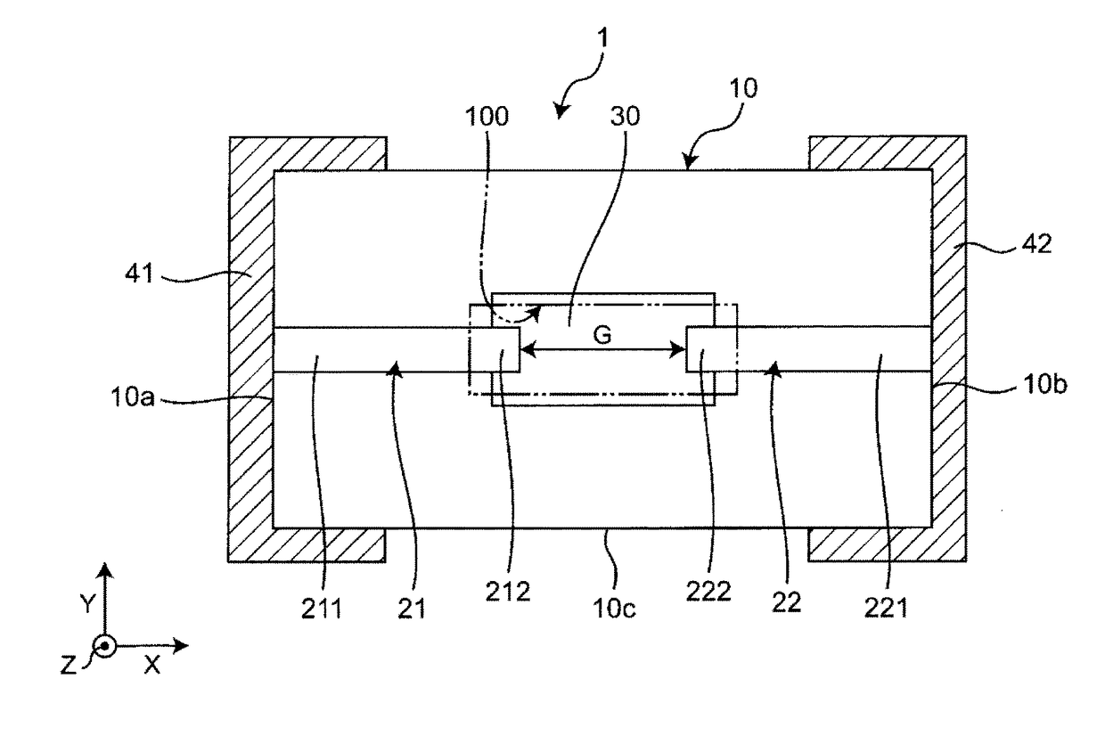
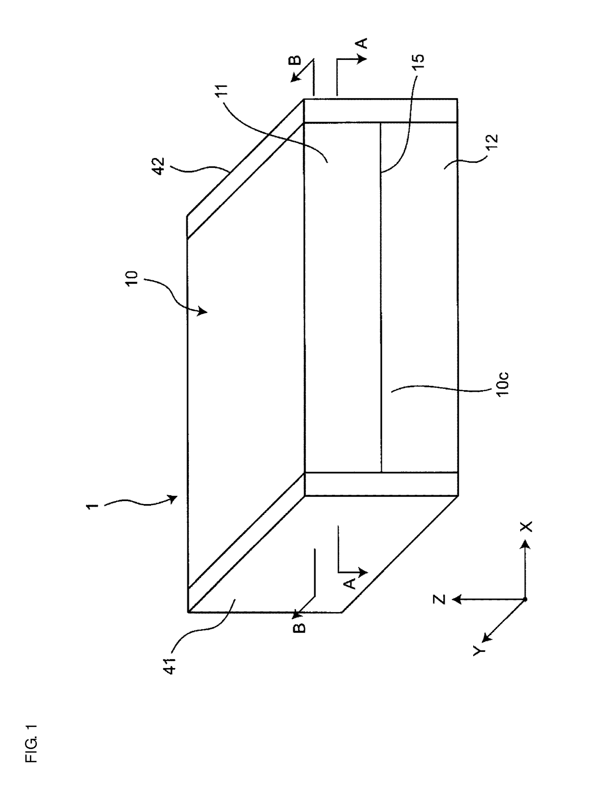
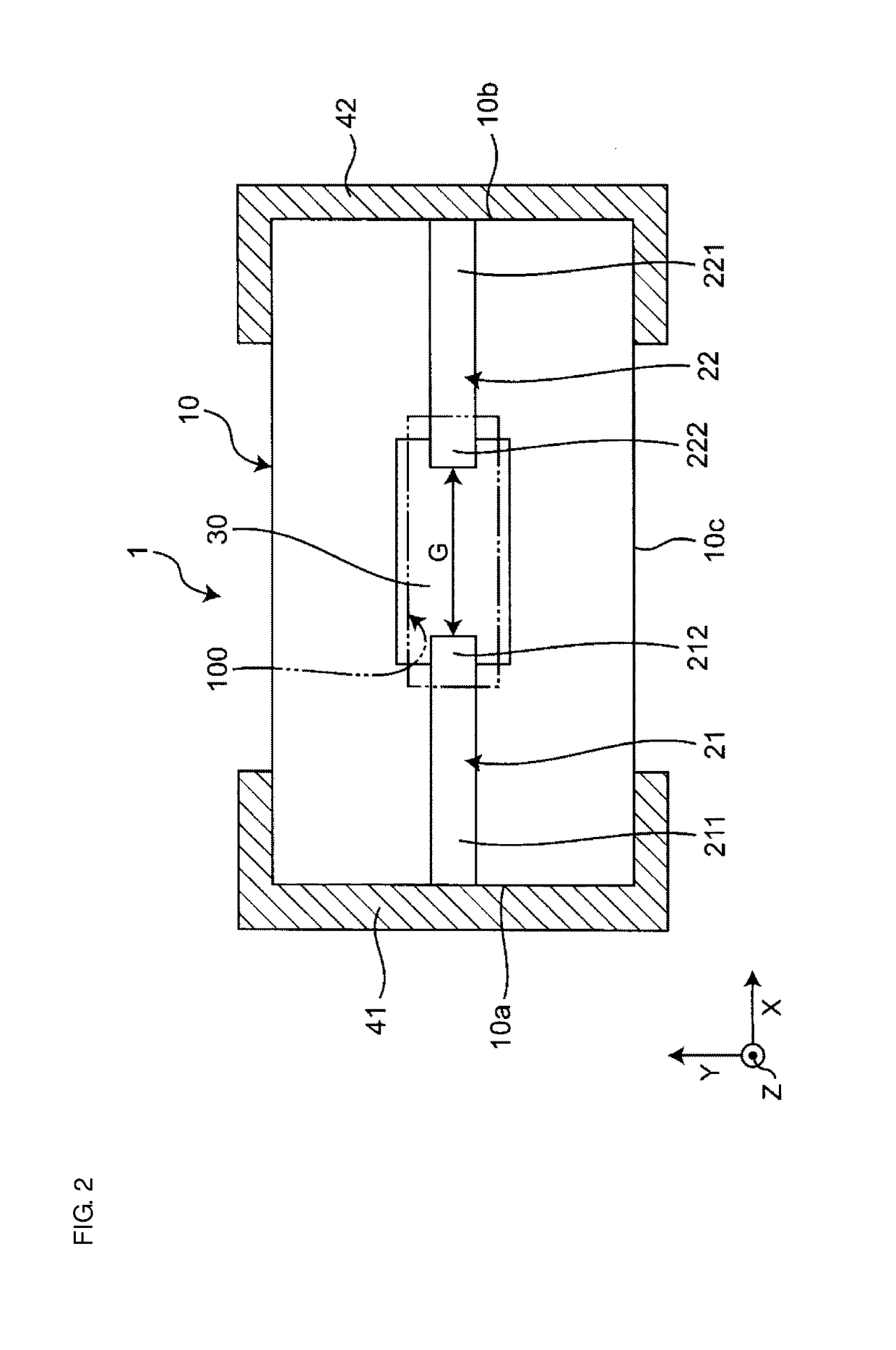
[0037]FIG. 1 is a perspective view showing an ESD protection device according to a first preferred embodiment of the present invention. FIG. 2 is a sectional view taken along a line A-A in FIG. 1. FIG. 3 is a sectional view taken along a line B-B in FIG. 1. As shown in FIGS. 1, 2 and 3, an ESD (Electro-Static Discharge) protection device 1 includes a bare unitary body 10, a first discharge electrode 21, a second discharge electrode 22, and a discharge auxiliary electrode 30 that are all disposed inside the bare unitary body 10, and a first outer electrode 41 and a second outer electrode 42 that are disposed on an outer surface of the bare unitary body 10.

[0038]The bare unitary body 10 preferably has a rectangular parallelepiped or substantially rectangular parallelepiped shape, and it has a length, a width, and a height. A direction of the length of the bare unitary body 10 is defined as an X direction, a direction of the width of the bare unitary body 10 is defined as a Y direction...

second preferred embodiment

[0067]FIG. 7A is an XY sectional view showing an ESD protection device according to a second preferred embodiment of the present invention. FIG. 7B is a sectional view taken along a line C-C in FIG. 7A. The second preferred embodiment is different from the first preferred embodiment in the direction in which the first discharge electrode and the second discharge electrode are opposed to each other. Only the differences between the first and second preferred embodiments are described below. It is to be noted that the same reference symbols in the second preferred embodiment as those in the first preferred embodiment denote similar elements and components to those in the first preferred embodiment, and hence description of those elements and components is omitted here.

[0068]In an ESD protection device 1A, as shown in FIGS. 7A and 7B, a direction in which a first discharge electrode 21A and a second discharge electrode 22A are opposed to each other is aligned or substantially aligned w...

third preferred embodiment

[0072]FIGS. 8A to 8C are each an XZ sectional view showing an ESD protection device according to a third preferred embodiment of the present invention. The ESD protection devices shown in FIGS. 8A to 8C are different from the first preferred embodiment in the shape of the cavity. Only the differences between the first and third preferred embodiments are described below. It is to be noted that the same reference symbols in the third preferred embodiment as those in the first preferred embodiment denote similar elements and components to those in the first preferred embodiment, and hence description of those elements and components is omitted here.

[0073]As shown in FIG. 8A, a sectional shape of a cavity 100B in an ESD protection device 1B is not triangular or substantially triangular, unlike the first preferred embodiment (FIG. 3). An inner surface defining a shape of the cavity 100B on the side closer to the first space 101 includes a circular arc surface, and an inner surface defini...


PUM


Abstract

An ESD protection device includes a bare unitary body, and a first discharge electrode and a second discharge electrode that are disposed inside the bare unitary body. The first discharge electrode and the second discharge electrode are opposed to each other with a gap interposed therebetween. The bare unitary body includes a cavity in which the gap between the first discharge electrode and the second discharge electrode is located, and to which the first discharge electrode and the second discharge electrode are exposed. A first space of the cavity on a side closer to the first discharge electrode is smaller than a second space of the cavity on a side closer to the second discharge electrode.

Description

CROSS REFERENCE TO RELATED APPLICATIONS[0001]This application claims the benefit of priority to Japanese Patent Application No. 2014-256648 filed on Dec. 18, 2014 and is a Continuation application of PCT Application No. PCT / JP2015 / 084241 filed on Dec. 7, 2015. The entire contents of each application are hereby incorporated herein by reference.BACKGROUND OF THE INVENTION[0002]1. Field of the Invention[0003]The present invention relates to an ESD protection device and a manufacturing method for the ESD protection device.[0004]2. Description of the Related Art[0005]An ESD protection device has been proposed in Japanese Unexamined Patent Application Publication No. 2013-168226, for example. The proposed ESD protection device includes a bare unitary body made of ceramic, and a first discharge electrode and a second discharge electrode that are disposed inside the bare unitary body. The first discharge electrode and the second discharge electrode are opposed to each other with a gap inter...

Claims


Application Information

Patent Timeline
Patent Type & Authority Applications(United States)
IPC IPC(8): H01T1/20H01T21/00H01T4/12
CPCH01T1/20H01T21/00H01T4/12
Inventor YASUNAKA, KATSUMIADACHI, JUN
Owner MURATA MFG CO LTD
Why Eureka
Try Eureka