Ultrasonic Flow Probe And Method Of Monitoring Fluid Flow In A Conduit

a technology of ultrasonic flow and conduit, which is applied in the direction of fluid speed measurement, measurement devices, instruments, etc., can solve the problems of saving time and cost during installation, and achieve the effect of reducing time and cos

Inactive Publication Date: 2017-08-31
POLLUTION CONTROL & MEASUREMENT EURO
View PDF1 Cites 2 Cited by
  • Summary
  • Abstract
  • Description
  • Claims
  • Application Information

AI Technical Summary

Benefits of technology

[0023]Such a method for monitoring fluid flow permits the fluid flow to be measured directly. Thus there is no need for a specially-angled spool-piece to be included into the conduit. This may reduce the time and cost associated with installing the probe. The adjusting of the primary axis to be at an angle to the mounting axis may allow the probe to be positioned at an angle most preferable for a given application. Re-adjustment of the already mounted probe may also be carried out.
[0024]The angle between the primary axis and the mounting axis may be adjusted to a value in the range of greater than zero degrees to less than 90 degrees. Thus it may be possible to set the primary axis at an angle to the average velocity of fluid flow. The angle between the primary axis and the mounting axis may be adjusted to zero during insertion of the probe into the conduit, and adjusted to a value greater than zero degrees and less than 90 degrees during the measuring. This may allow insertion of the flow probe into conduits of a variety of shapes and sizes. The angle between the primary axis and the mounting axis may be adjusted by an actuation system, which may be automated. The actuation system may allow the angle of the primary axis to be remotely altered. This may allow measurements to be taken at different angles without interfering with the fluid flow in the conduit in order to alter the angle of the primary axis.
[0025]The method may include a step of adjusting the frame by rotating the frame about the mounting axis prior to the measuring. This may allow the primary axis to be positioned at an angle to fluid flow which is even more preferable for a given application. The rotating of the frame about the mounting axis may be carried out by an automated rotation system. This may allow rotation about the mounting axis to take place without interfering with or stopping the fluid flow in the conduit.
[0026]The method may include a step of adjusting the separation of the transducers prior to the measuring. The adjustment may be performed by an actuation system, which may be automated. Adjustable separation of the transducers may allow the sample region of the flow probe to be adjusted to a size which is most preferable for a given application. The transducers may be at a first separation during the insertion of the probe into the conduit and adjusted to a second position prior to the measuring. This may allow the flow probe to be inserted into conduits of a variety of shapes and sizes. The altering of the transducer separation may be done from outside of the conduit by an automated actuation system. This may allow the transducer separation adjustment to take place without interfering with or stopping the fluid flow in the conduit.

Problems solved by technology

That may save time and cost during installation of the probe.

Method used


Image

  • Ultrasonic Flow Probe And Method Of Monitoring Fluid Flow In A Conduit
  • Ultrasonic Flow Probe And Method Of Monitoring Fluid Flow In A Conduit
  • Ultrasonic Flow Probe And Method Of Monitoring Fluid Flow In A Conduit

Examples


Embodiment Construction

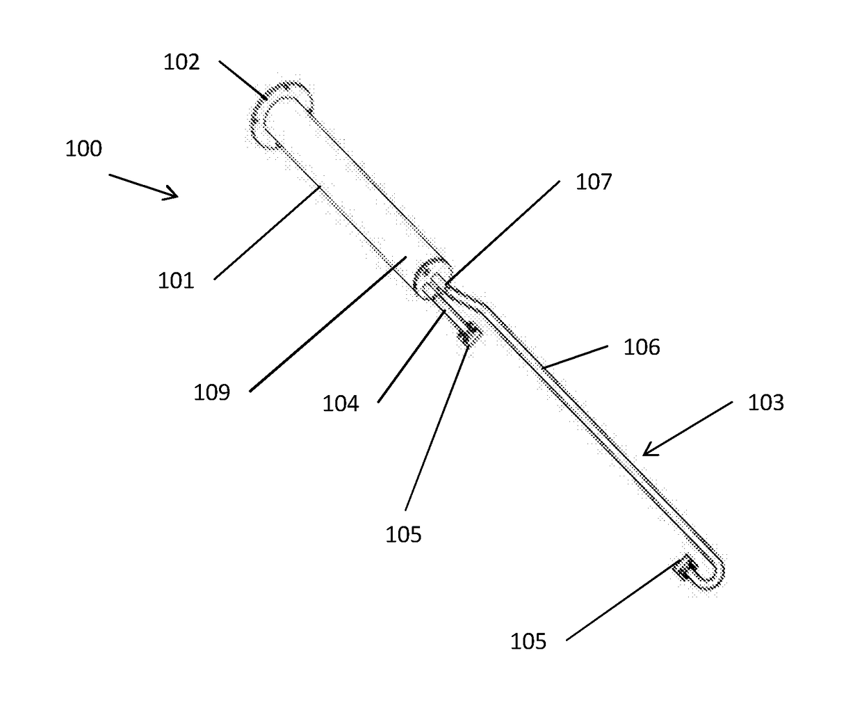
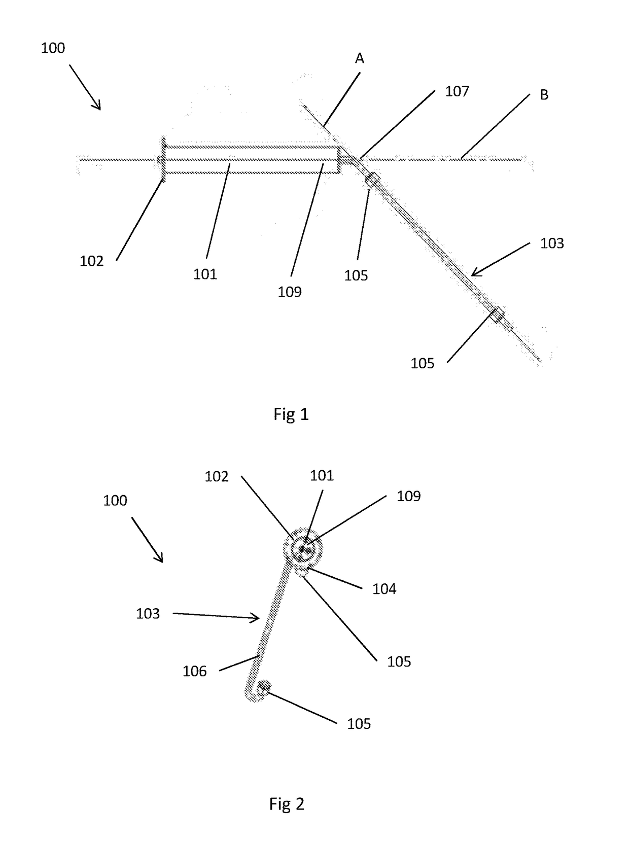
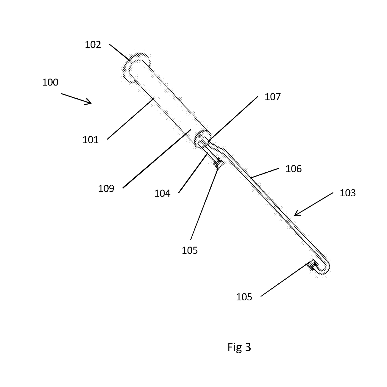
[0033]FIGS. 1, 2 and 3 show a first embodiment of an ultrasonic flow probe 100 comprising: a mounting member 101, a frame 103 mounted on the member 101, and two ultrasonic transducers 105 mounted on the frame 103.

[0034]The mounting member 101 is a cylindrical member that, when the probe 100 is mounted on a surface, extends away from the surface with the axis of the cylinder being aligned along a mounting axis B. At one end of the mounting member 101 there is a mounting plate 102 which is arranged to be mounted on the surface on which the probe 100 is mounted. For example, the mounting plate 102 may be fixed to or through the surface. Since the mounting plate 102 in this embodiment is aligned with the surface, the mounting axis B is perpendicular to the mounting plate 102.

[0035]The frame 103 consists of two arms 104, 106. One end of each arm 104, 106 is mounted to the free end of the mounting member 101. An ultrasonic transducer 105 is mounted to the other end of each arm 104, 106. T...


PUM


Abstract

An ultrasonic flow probe (100) comprising a mounting member (101) for mounting on a surface of a conduit and thereby defining a mounting axis (B) perpendicular to the surface, a frame (103) mounted on the mounting member (101), and a plurality of ultrasonic transducers (105) mounted on the frame (103) and aligned along a primary axis (A); wherein the frame (103) and mounting member (101) are configurable such that the primary axis (A) is at an angle to the mounting axis (B) so that, in use, ultrasound passing between the transducers (105) travels at an angle to fluid flowing in the conduit.

Description

FIELD OF THE INVENTION[0001]The present invention concerns an ultrasonic flow probe and a method of monitoring fluid flow in a conduit, for example a stack. More particularly, but not exclusively, this invention concerns an ultrasonic flow probe for monitoring fluid flow in a conduit.BACKGROUND OF THE INVENTION[0002]It is often desirable to know the characteristics of fluid flow in a conduit, for example a stack. This may be due to a regulatory requirement to monitor emissions, or a desire to improve the efficiency of an industrial process. Characteristics of fluid flow being measured may include: the average velocity of the fluid, the velocity profile of the fluid, and / or any departure from lamina flow within the fluid.[0003]There is a variety of techniques for measuring fluid flow. These include optical methods, electrical methods and ultrasonic methods. In a typical ultrasonic method ultrasonic transducers emit and receive contra-propagating ultrasonic waves along a path, having ...

Claims


Application Information

Patent Timeline
Patent Type & Authority Applications(United States)
IPC IPC(8): G01F1/66G01P5/24
CPCG01F1/662G01P5/245G01F1/667
Inventor MILLINGTON, ROGER BRADLEYREID, ARCHIBALD SIMON
Owner POLLUTION CONTROL & MEASUREMENT EURO
Why Eureka
Try Eureka