

Electronic Control Device
- Summary
- Abstract
- Description
- Claims
- Application Information
AI Technical Summary
Benefits of technology
Problems solved by technology
Method used
Image

Examples
first embodiment
[0013]Hereinafter, a configuration and an operation of an electronic control device according to a first embodiment of the present invention will be described with reference to FIGS. 1 and 2.
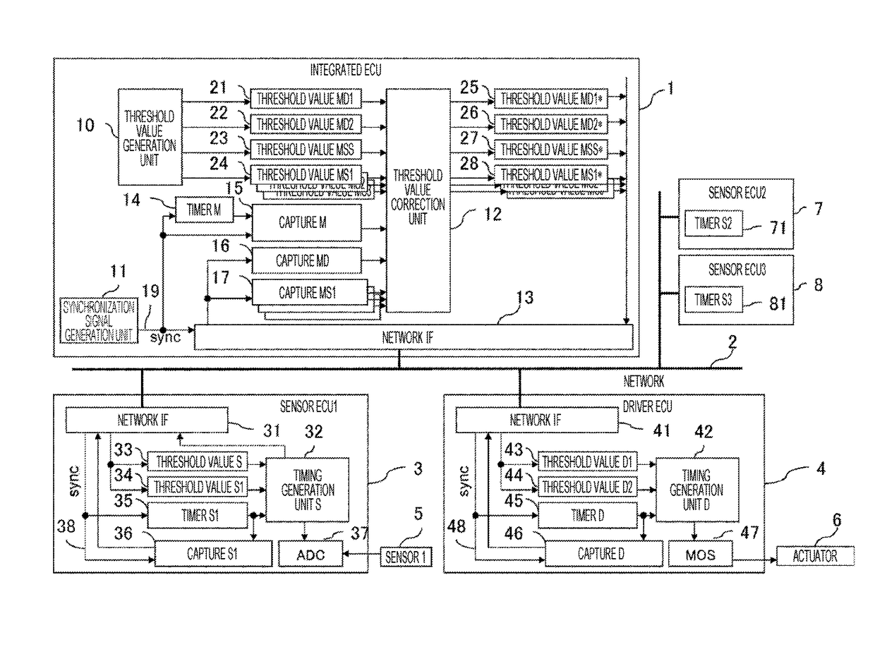
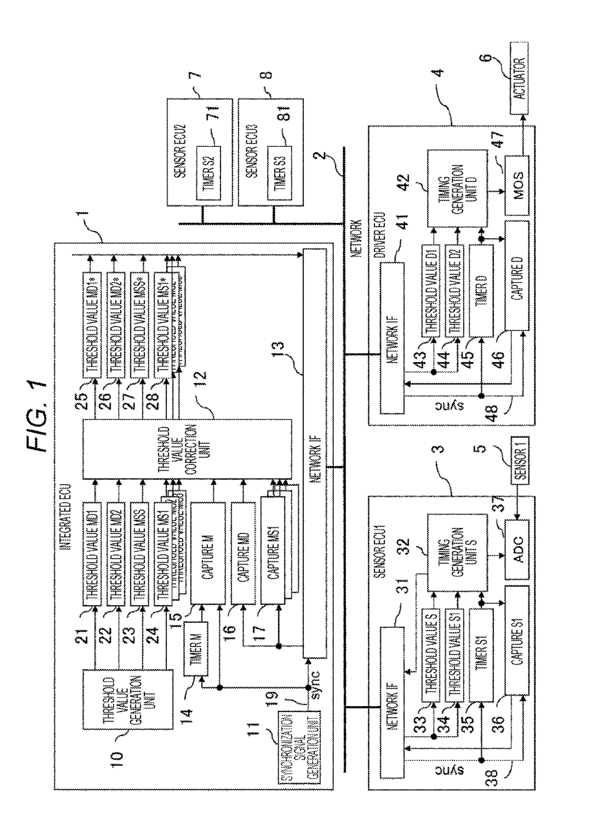
[0014]FIG. 1 is an overall block diagram of a current control device according to the first embodiment of the present invention.
[0015]The electronic control device includes a driver ECU (4) that drives an actuator (6), a sensor ECU1 (3) that samples data from a sensor (5), a sensor ECU2 (7) that samples data from various sensors (not illustrated), a sensor ECU3 (8), and an integrated ECU (1) that calculates command values to the driver ECU (4) based on various sensor data. Each of the ECUs is connected with a network (2), and transmits and receives data for control via the network.
[0016]The integrated ECU (1) includes a threshold value generation unit (10) for generating a threshold value for indicating timings to the sensor ECU1 (3), the sensor ECU2 (7), the sensor ECU3 (8), and the driver ECU ...
second embodiment
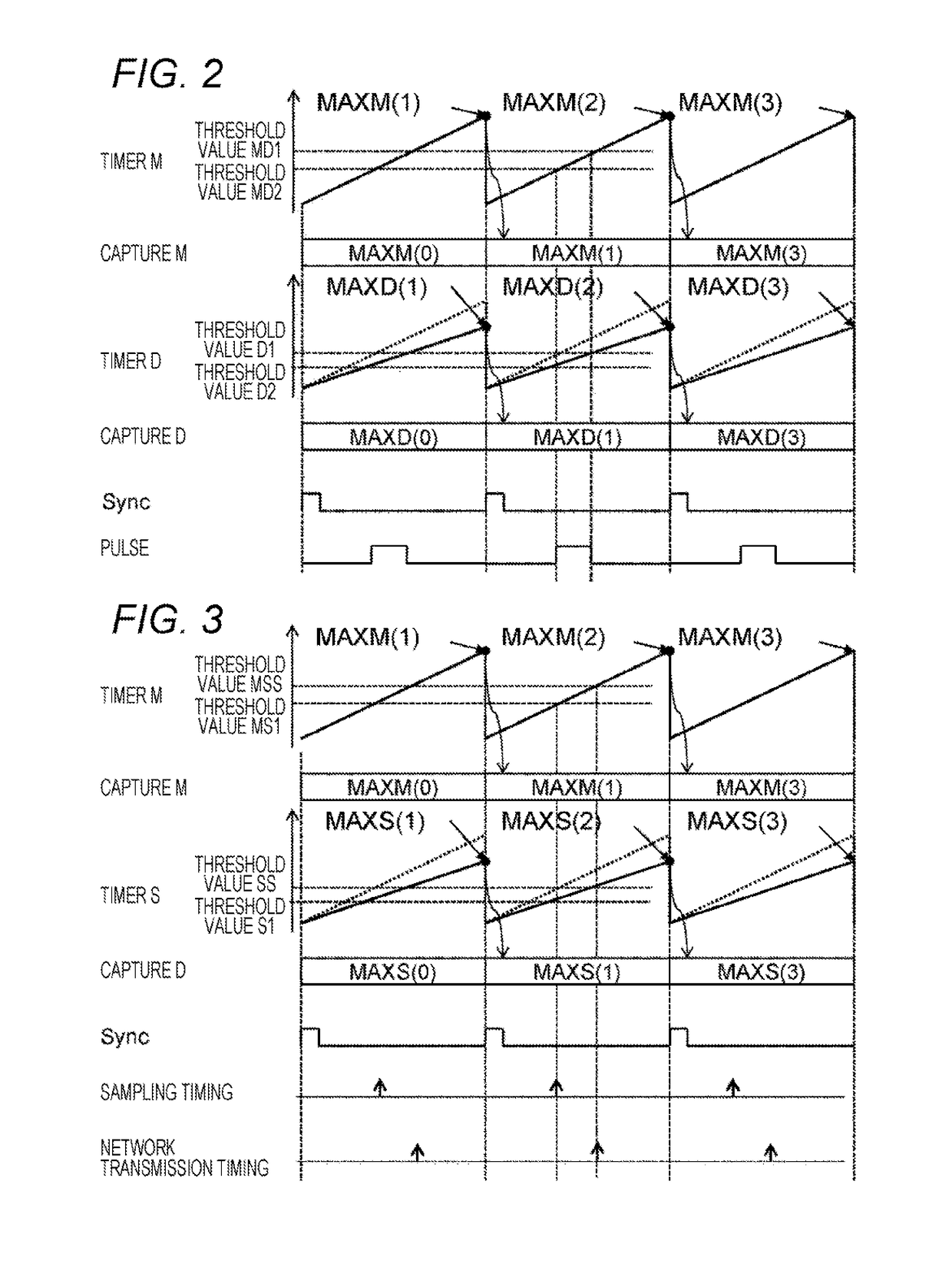
[0041]Hereinafter, a sensor data sampling operation of an electronic control device according to a second embodiment of the present invention will be described with reference to FIG. 3.
[0042]In the integrated ECU (1), a threshold value S and a threshold value S1 are used to generate timings for sampling a sensor data and transferring the data on the network. Here, since there is a difference in speed between the timer M (14) in the integrated ECU (1) and the timer S (35) in the sensor ECU1 (3), there is a problem that a timing deviation occurs if the same threshold value is used. Therefore, the threshold value is corrected by the aforementioned method. In this example, the timer S is slower in counting up than the timer M indicated by the dotted line. By correcting the threshold value according to the formula described above, it is possible to generate timings similar to the timings for sampling and transferring the data based on the timer M on the side of the sensor ECU.
third embodiment
[0043]Hereinafter, a network transfer operation of an electronic control device according to a third embodiment of the present invention will be described with reference to FIG. 4.
[0044]In the integrated ECU (1), the threshold value S1, the threshold value S1, and a threshold value S3 are used to generate data transferring timings of the sensor ECU1, the sensor ECU2, and the sensor ECU3. Here, since there is a difference in speed between the timer M (14) in the integrated ECU (1) and the timer S1 (35), the timer S2 (71), and the timer S3 (81) in the sensor ECUs, there is a problem that a timing deviation occurs if the same threshold value is used. Therefore, by correcting the threshold value according to the formula described above, it is possible to generate timings similar to the data transmission timings based on the timer M on the side of each of the sensor ECUs. In this example, by transferring the data at equal intervals, a data collision is avoided and the data is transferred...
PUM
 Abstract
Description
Claims
Application Information