Bone clamp

a bone clamp and drill guide technology, applied in the field of surgical instruments, can solve the problems of insufficient adjustment of the longitudinal and transverse angles of the drill guide in relation to the longitudinal axis of the jaws of the bone clamp of the prior ar

Active Publication Date: 2017-09-21
KIM ALEXANDER D +1
View PDF10 Cites 3 Cited by
  • Summary
  • Abstract
  • Description
  • Claims
  • Application Information

AI Technical Summary

Benefits of technology

[0004]The instant invention provides a solution to the above mentioned problem with prior art bone clamps. In one embodiment the instant invention is a bone clamp comprising a first jaw, an opposed second jaw and a drill guide, the drill guide being attached to the first jaw so that bone held between the first jaw and the second jaw can be drilled by a drill inserted through the drill guide, the first jaw having a longitudinal axis, wherein the improvement comprises the drill guide being ball shaped at one distal end thereof, the ball shaped end of the drill guide being positioned sufficiently within and retained within a corresponding cavity of the first jaw so that the angle of the drill guide can be adjusted to compound angles in the longitudinal and transverse directions in relation to the longitudinal axis of the first jaw.

Problems solved by technology

Despite the significant benefits provided by prior art bone clamps, none of the bone clamps of the prior art provide a drill guide having sufficient adjustment with regard to compound angles in the longitudinal and transverse directions in relation to the longitudinal axis of the jaws of the bone clamp.

Method used


Image

  • Bone clamp
  • Bone clamp
  • Bone clamp

Examples


Embodiment Construction

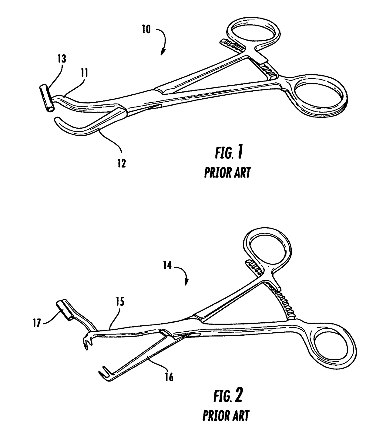
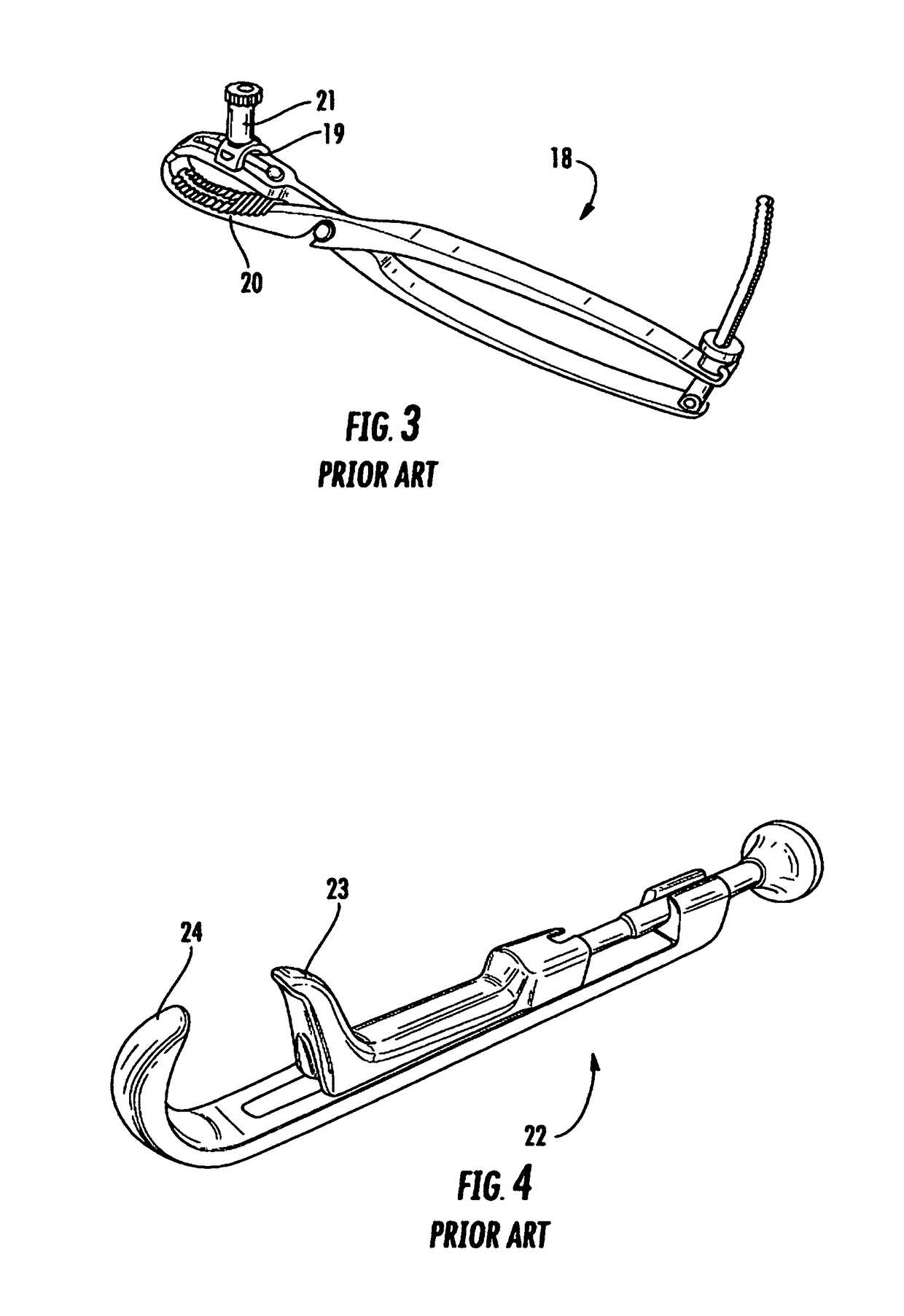
[0025]By way on introduction, a number of bone clamps of the prior art will be described. The instant invention is an improvement upon such prior art bone clamps. Referring now to FIG. 1, therein is shown a perspective view in full of a locking forceps bone clamp 10 of the prior art having a fixed angle drill guide 13 attached to one jaw 11 thereof, the other jaw 12 thereof having a hook shape. The bone clamp 10 is similar to the bone clamp described in U.S. 5,725,532 to Shoemaker. Referring now to FIG. 2, therein is shown a perspective view in full of a locking forceps bone clamp 14 of the prior art having a fixed angle drill guide 17 attached to one jaw 15 thereof, the other jaw 16 thereof terminating in a toothed shape. Referring now to FIG. 3, therein is shown a perspective view in full of a locking pliers bone clamp 18 of the prior art having an adjustable angle drill guide 21 attached to one jaw 19 thereof, the other jaw 20 thereof having a conventional pliers shape. The bone ...


PUM


Abstract

A bone clamp having a first jaw, an opposed second jaw and a drill guide, the drill guide being attached to the first jaw so that bone held between the first jaw and the second jaw can be drilled by a drill inserted through the drill guide, the first jaw having a longitudinal axis. The drill guide can be ball shaped at one distal end thereof that is positioned sufficiently within and retained within a corresponding cavity of the first jaw so that the angle of the drill guide can be adjusted to compound angles in the longitudinal and transverse directions in relation to the longitudinal axis of the first jaw. The bone clamp preferably comprises an organic polymer that is relatively transparent to X-rays.

Description

BACKGROUND OF THE INVENTION[0001]The instant invention relates to surgical instruments and more particularly to bone clamping devices. Even more particularly, the instant invention relates to bone clamps having guides for guiding bone drills so that a fractured bone can be temporarily held in place when drilled to produce a drilled passageway in the fractured bone followed by the insertion of a bone screw into the drilled passageway to permanently secure the fractured bone.[0002]A number of bone clamp designs are available to the modern orthopedic surgeon. U.S. Pat. No. 5,725,532 to Shoemaker disclosed a locking forceps design having a fixed drill guide in one jaw thereof U.S. Pat. No. 8,080,045 to Wotton, III, disclosed a locking forceps design having a fixed drill guide in a coaxially articulated jaw arrangement. U.S. Pat. No. 3,835,849 to McGuire discloses a c-clamp design having a sliding drill guide in one jaw thereof USPAP 2008 / 0009871 of Orbay et al. discloses a c-clamp desig...

Claims


Application Information

Patent Timeline
Patent Type & Authority Applications(United States)
IPC IPC(8): A61B17/28A61B17/17
CPCA61B17/282A61B2017/2808A61B17/17A61B17/8866
Inventor KIM, ALEXANDER D.KIM, DAVID C.
Owner KIM ALEXANDER D
Why Eureka
Try Eureka