Reset forceps

A technology of reducing forceps and forceps body, applied in the field of reducing forceps, can solve the problems of increasing patient pain, inconvenience to doctors, and aligning both ends, and achieves the effect of reducing work intensity and pain

Active Publication Date: 2016-02-24
江苏惠骨医疗器械有限公司
View PDF9 Cites 0 Cited by
  • Summary
  • Abstract
  • Description
  • Claims
  • Application Information

AI Technical Summary

Problems solved by technology

The commonly used reduction forceps are mainly composed of two X-shaped forceps arms hinged, the front end is used as a clamp, and the rear end is used as a handle. After a fracture, the two broken bones will be staggered due to the pulling and traction of the muscles. Overlapping, when the broken bone is reset, at least two reduction forceps should be used to hold the two broken bones respectively, and the two broken bones should be pulled apart by the medical staff to the reset position and fixed with a steel plate. The moving position of the two broken bones The size needs to be adjusted manually, which makes it difficult to align the two ends of the broken bone. Sometimes, after the broken bone is reset, when the bone clamp is removed and the plate is fixed, the broken bone returns to its original dislocation state, which brings inconvenience to the doctor. It also increases the pain of the patient

Method used


Image

  • Reset forceps
  • Reset forceps
  • Reset forceps

Examples


Embodiment Construction

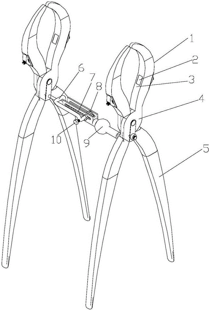
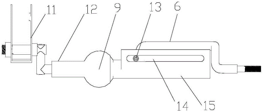
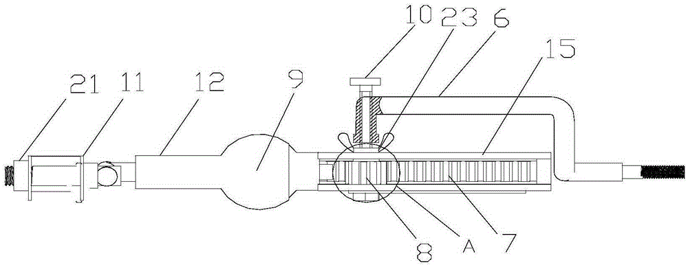
[0023] figure 1 It is a structural schematic diagram of the present invention; figure 2 It is a structural schematic diagram of the connecting rod of the present invention; image 3 for figure 2 top view of Figure 4 is the schematic diagram of the structure of clamp body Ⅰ; Figure 5 for image 3 Enlarged image at A in the middle; Figure 6 for Figure 4 Enlarged view of middle B; Figure 7 It is a structural schematic diagram of the gear 8 of the present invention. As shown in the figure, the reset clamp in this embodiment includes at least two bone clamps 4 and a connecting rod connecting two adjacent bone clamps 4, such as image 3 As shown, the connecting rod includes a connecting rod body 7, an adjusting rod 6, and a longitudinal adjustment mechanism that moves the connecting rod body 7 relative to the adjusting rod 6 along its longitudinal direction. The rack on 7, the gear 8 that is rotatably connected to the adjustment rod 6 and cooperating with the gear ra...


PUM


Abstract

The invention discloses a pair of reduction forceps. The pair of the reduction forceps comprises at least two bone clamping forceps bodies and a connection rod connecting the two bone clamping forceps. The connection rod comprises a connection rod body, an adjusting rod and a longitudinal adjusting mechanism enabling the connection rod body to move relative to the adjusting rod in the longitudinal direction. According to the reduction forceps, people only need to adjust rotation of a gear so that broken bones can move relatively along the connection rod in the longitudinal direction, and accordingly reduction of the broken bones is achieved. Manual adjustment is not needed, the positions of the broken bones do not need to be fixed, after broken bone reduction is finished, the relative position of the two bone clamping forceps bodies can be locked through the connection rod body, and accordingly the relative position of the broken bones is locked. The situation that the broken bones are dislocated after subsequent operation of an operation is avoided, so that labor intensity of medical staff is lightened, and pains of patients are relieved.

Description

technical field [0001] The invention relates to the field of medical instruments, in particular to a reset forceps. Background technique [0002] After the fracture, it is generally necessary to use bone-holding forceps to reset the broken bone and fix it with plates, screws, etc. The commonly used reduction forceps are mainly composed of two X-shaped forceps arms hinged, the front end is used as a clamp, and the rear end is used as a handle. After a fracture, the two broken bones will be staggered due to the pulling and traction of the muscles. Overlapping, when the broken bone is reset, at least two reduction forceps should be used to hold the two broken bones respectively, and the two broken bones should be pulled apart by the medical staff to the reset position and fixed with a steel plate. The moving position of the two broken bones The size needs to be adjusted manually, which makes it difficult to align the two ends of the broken bone. Sometimes, after the broken bon...

Claims


Application Information

Patent Timeline
Patent Type & Authority Patents(China)
IPC IPC(8): A61B17/28A61B17/56
CPCA61B17/2833A61B17/8866
Inventor 喻一东马秋野马奔杨利梁红所谢山林
Owner 江苏惠骨医疗器械有限公司
Why Eureka
Try Eureka