[0022]Turning now to the detailed description of the preferred arrangement or arrangements of the present invention, it should be understood that the inventive features and concepts may be manifested in other arrangements and that the scope of the invention is not limited to the embodiments described or illustrated. The scope of the invention is intended only to be limited by the scope of the claims that follow.
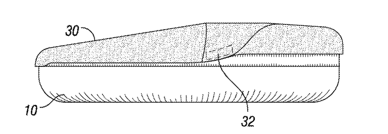
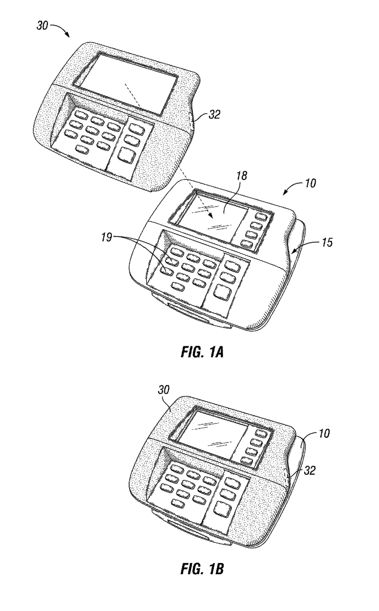
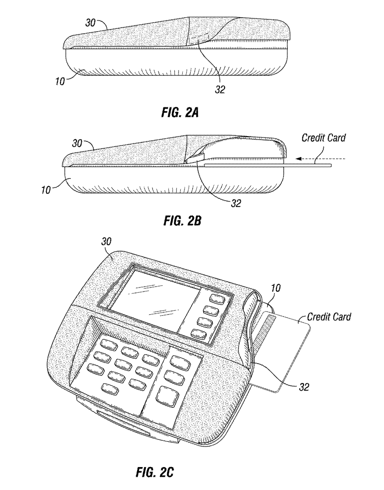
[0023]As shown in FIGS. 1A, 1B, 2A, 2B, and 2C, a credit/debit card reader is generally indicated by the numeral 10. The card reader 10 includes a slot 15 at the right for sliding a credit card or debit card for completing a purchase or payment transaction. The card reader 10 further includes a screen 18 and buttons 19 for displaying transaction information and taking additional information such as personal identification numbers (PIN) or zip code information or other authenticating information.
[0024]Aligned to fit over the card reader 10 is a skimmer 30. The skimmer 32 is a device created by thieves for collecting credit card and debit card information illicitly and surreptitiously, while neither the vendor, the customer nor the attendant are aware. A thief may position the skimmer 30 by distracting the attendant with a request for a package of cigarettes that require the attendant to turn his back toward the card reader 10 for a few seconds. The thief may have the skimmer 30 within a jacket and quickly slip it over the legitimate credit/debit card reader 10. The skimmer 30 may be left in place for a period of time to collect credit and debit card information. The skimmer includes memory (not shown) and card reader device 32 keeping track of each card run through the credit card slot along with any key strokes inputted during a legitimate transaction.
[0025]After a period of time, the thief will come back to the store recover the skimmer for downloading the data now collected. It is not inconceivable that the thief may come into the store to swap out skimmers 30 putting a new one over the credit/debit card reader 10 to collect additional information while the first skimmer 30 is taken back for downloading information.
[0026]The present invention has been created to provide a simple, low cost method of interfering with thieves and their fraudulent efforts. The invention is more particularly shown in FIGS. 3, 4A, 4B, and 4C as blockers 41 and 42. The blockers 41 and 42 are three dimensional structures constructed or robust material such as an acrylic and glued or adhered onto the credit/debit card reader with a strong epoxy. Only one blocker 41 or 41 is needed to meet the basic intent of the invention, but additional blockers should be inexpensive and would create a randomness to the card readers 10 and would require more time for the thief to try and remove to fit the skimmer 30 onto the card reader 10. The blockers 41 and 42 may be installed anywhere on the front of the card reader 10 where the skimmer 30 may be expected to cover. It is preferred that the blockers 41 and 42 would have an appealing look such as logo information for the store and have an irregular shape, such as one that would go with a logo. If there are more than one card reader 10 in a store, each such reader may and should preferably have a different arrangement of the blockers 41 and 42.
[0027]As best shown in FIGS. 2B and 4A, the reader 10 has an axis (as shown) along which the credit card or debit card is slid along the card slot 15. Without the blockers 41 and 42 in place, the skimmer axis would align with the reader axis when the skimmer 30 is arranged flush with card reader 10. With the blockers in place, as best shown in FIGS. 4B and 4C, the thickness dimension of the blockers 41 and 42 would alter the respective axes so that they are prevented from aligning. While this misalignment may be enough to prevent the skimmer 30 from illicitly capturing the credit or debit card information, more ideally the unauthorized presence of the skimmer 30 on the card reader 10 will be revealed to the attendant and the customer and the skimmer 30 will be removed. The actual thief may not be easily caught, but frustrating the efforts of the thieves is the primary purpose of the blockers 41 and 42.
[0028]Manufacturers of carder reader devices all have their own proprietary shape, look and feel. The blockers 41 and 42 are hopefully useful with all such arrangements. The thieves have surely figured out how to make very convincing looking covers for the most common card readers. As the inventors were first presented with the problem of skimmers 30, they were told that one of the skimmers 30 that were recovered prior to the thief being able to return to the store and recover the skimmer and the data thereon, that the reason it was noticed is that the skimmer cover appeared very new and was covering a card reader that had been quite beat up and scratched. In this case, the store owner, cashiers and consumers were lucky that the new appearing skimmer 30 turned out to be quite noticeable. However, law-abiding store owners, cashiers and innocent consumers should not have to depend on luck alone to help prevent illegal credit card skimming.
[0029]In the second application, some card readers require the credit or debit card to be inserted into the device and then pulled back out. Such a card reader is shown in FIGS. 5, 6A and 6B and indicated by the number 60. A skimmer 70 is designed to overlay the insertion type of card reader 60. The skimmer 70 includes some type of reader 72 along with some embedded memory (not shown) and is intended to be innocuous and unnoticeable. As shown in FIGS. 7 and 8, blockers 41 are positioned on flat or generally flat surfaces to block the installation of a skimmer. The blockers 41 are round dot type blockers while blocker 42 is shown with a triangular profile. Other shapes are also suitable. Being an inexpensive but robust material such as a rigid plastic is ideal, but wood and metal blockers would work if a strong adhesive were used. As shown in FIG. 8, the skimmer 70 will be quite noticeable if left loosely on the card reader 60.
[0030]In closing, it should be noted that the discussion of any reference is not an admission that it is prior art to the present invention, especially any reference that may have a publication date after the priority date of this application. At the same time, each and every claim below is hereby incorporated into this detailed description or specification as an additional embodiment of the present invention.
[0031]Although the systems and processes described herein have been described in detail, it should be understood that various changes, substitutions, and alterations can be made without departing from the spirit and scope of the invention as defined by the following claims. Those skilled in the art may be able to study the preferred embodiments and identify other ways to practice the invention that are not exactly as described herein. It is the intent of the inventors that variations and equivalents of the invention are within the scope of the claims while the description, abstract and drawings are not to be used to limit the scope of the invention. The invention is specifically intended to be as broad as the claims below and their equivalents.