
Gas Inflatable Balloons

Active Publication Date: 2017-10-05
ZURU (SINGAPORE) PTE LTD
View PDF0 Cites 7 Cited by
  • Summary
  • Abstract
  • Description
  • Claims
  • Application Information

AI Technical Summary

Benefits of technology

The patent describes a method for inflating balloons using inflation tubes. The method involves a duckbill valve for each inflation conduit, which prevents deflation of the balloon and leaves each conduit as a tether of the balloon. After inflation, the knots of the inflation tubes are tightly secured to create a closure and prevent fluid from escaping the balloon and tube. The technical effect of this patent is the efficient and effective inflation of balloons using inflation tubes with duckbill valves and secure knots.

Problems solved by technology

Inflating of balloons (such as party balloons) from a flaccid state with gas can be time consuming.
This can be difficult if the spout is very inelastic or short.
The process of inflating, sealing and anchoring balloons can hence take a long time.

Method used


Image

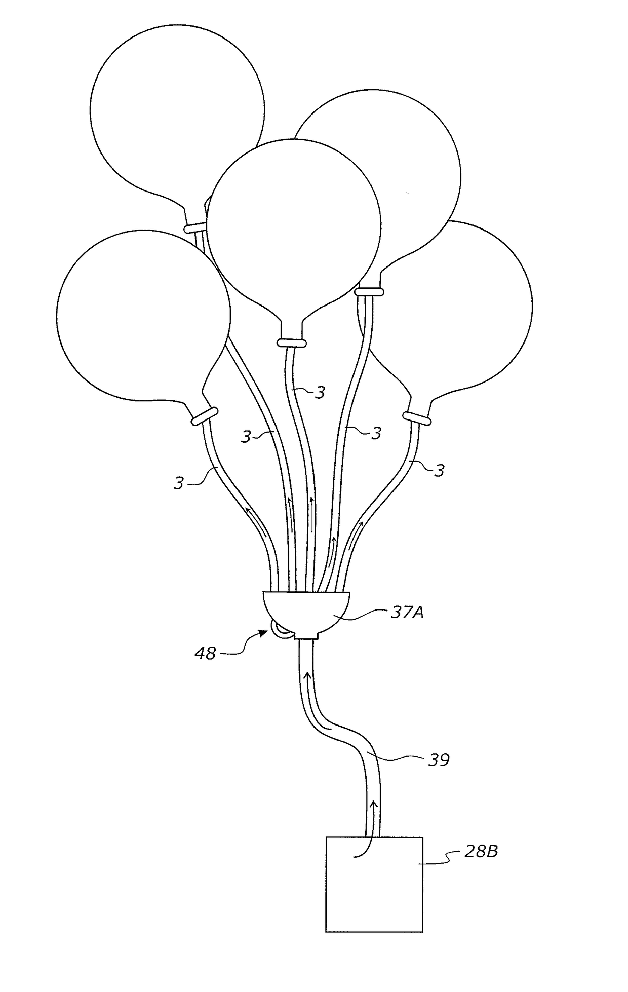
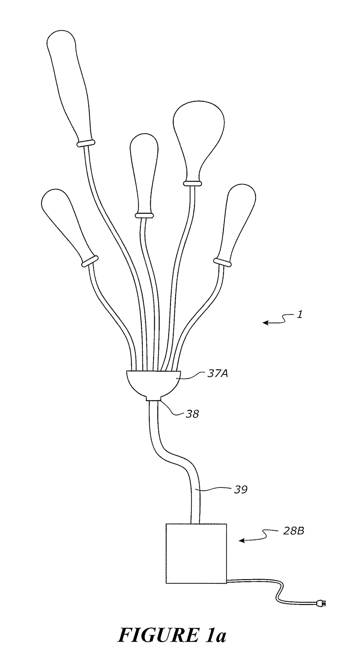
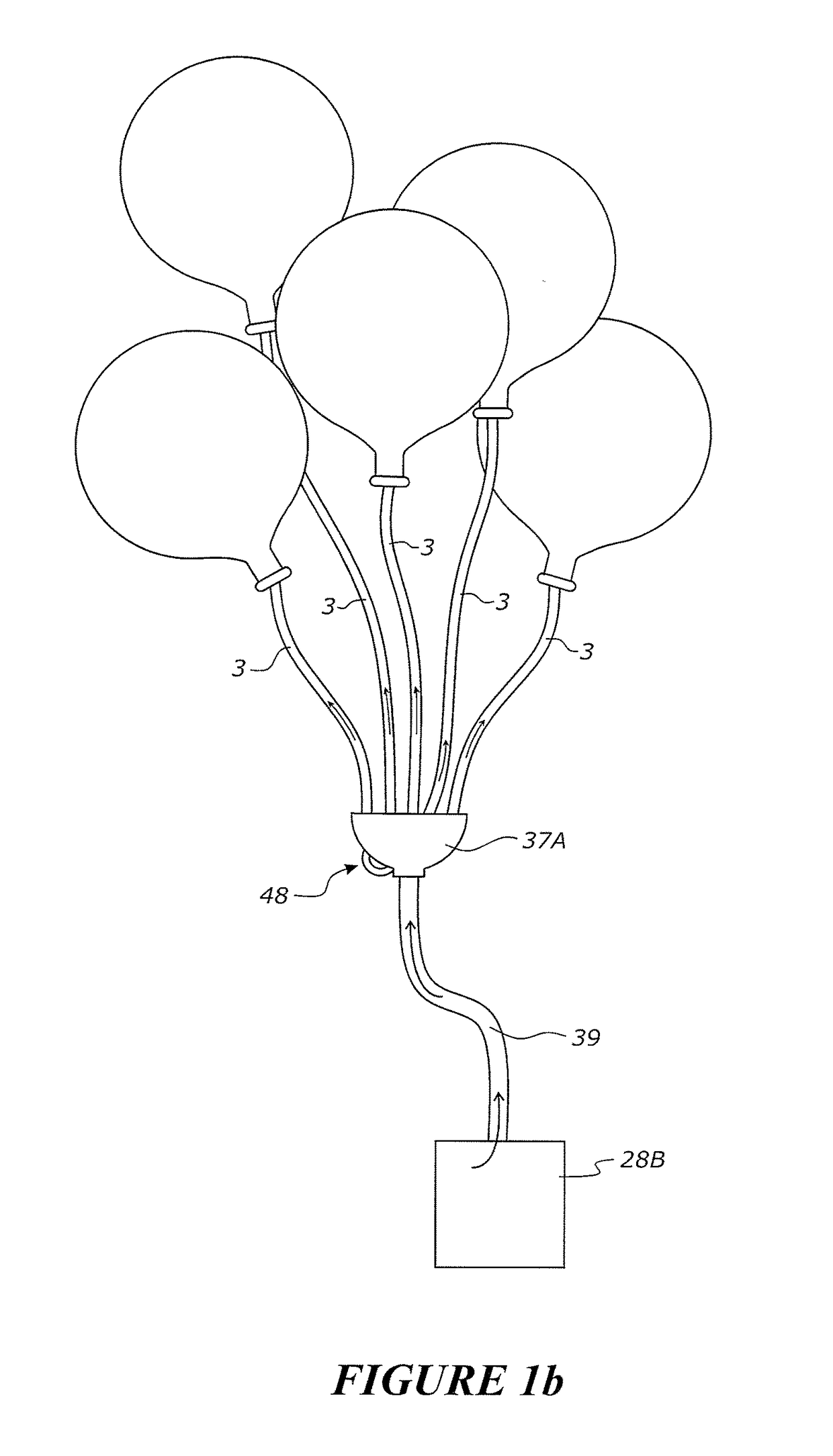
  • Gas Inflatable Balloons
  • Gas Inflatable Balloons
  • Gas Inflatable Balloons

Examples


Embodiment Construction

[0245]Reference will now be made to various components and variations of such components at least some of which are shown in the accompanying drawings, that can be used for executing the present invention.

[0246]With reference to FIG. 1c and 1d a balloon and tether assembly 1 is shown. The balloon and tether assembly includes a balloon 2 and tether 3.

[0247]The balloon is able to receive gas such as air via the tether to cause the balloon to be inflated. The balloon in FIG. 1c is shown inflated from its flaccid condition shown in FIG. 1d. The balloon's flaccid condition may correspond to the gas pressure inside the balloon being the same as ambient air pressure. In some situations, inflation of the balloon may involve increasing the gas pressure from a first pressure that is already above atmospheric pressure to a higher pressure.

[0248]The balloon is preferably of an elastic flexible material so that it can increase in volumetric displacement and increase in internal gas pressure when...


PUM


Abstract

A tethered balloon assembly the balloon, to be inflated via the tether which is to be subsequently closed by a one way valve to keep the balloon inflated and allow additional inflation as desired, controllable by its tether.

Description

BACKGROUND OF THE INVENTIONField of the Invention[0001]The present invention relates to gas inflatable balloons.Description of the Related Art[0002]Inflating of balloons (such as party balloons) from a flaccid state with gas can be time consuming. Inflation is typically done by placing a person's mouth on the spout of a balloon and breathing air into the balloon. The spout of the inflated balloon is then sealed, normally by the person tying a knot in the spout. This can be difficult if the spout is very inelastic or short. Often party balloons are displayed by anchoring them to ceilings or walls of the like. Mostly they will hang from their anchor point unless filled with a gas lighter than air. The anchoring of a balloon usually requires the tying of a string to the spout of the balloon. The string is then tied or pinned at or near its free end to anchor the balloon in place. This adds further time to the process of displaying inflated balloons at a party or other function. For par...

Claims


Application Information

Patent Timeline
IPC IPC(8): A63H27/10
CPCA63H27/10A63H2027/1033A63H2027/1091A63H2027/1075A63H2027/1083A63H2027/1041
Inventor MOWBRAY, MATHEW PETER
Owner ZURU (SINGAPORE) PTE LTD
Learn More