Treatment apparatus for treating a surface of a body

a treatment apparatus and body technology, applied in the direction of electric devices, basic electric elements, semiconductor/solid-state device manufacturing, etc., can solve the problems of ring chambers having to be moved, apparatus have considerable disadvantages, and the corresponding treatment steps cannot be carried out in a closed environment, so as to achieve simple and reliable exchange, flexible and simple in use

Inactive Publication Date: 2017-10-05
LEVITRONIX
View PDF6 Cites 0 Cited by
  • Summary
  • Abstract
  • Description
  • Claims
  • Application Information

AI Technical Summary

Benefits of technology

[0018]Starting from the prior at, it is therefore an object of the invention to propose a treatment apparatus for treating a surface of a body with at least two different treatment media, in particular for treating a disk-shaped wafer which allows the different treatment media used to be collected separately and specifically to be resupplied to the treatment process for reuse. In this respect, problems with the ring chambers movable in the vertical direction known from the prior art should be avoided. The treatment apparatus should be flexible and simple in use, and in particular permit a simple and reliable exchange, automated where possible, of the bodies to be treated.

Problems solved by technology

Damaging, e.g. corrosive or toxic liquids are also commonly used so that the corresponding treatment steps can only be carried out in a closed environment for environmental and safety reasons.
However, such apparatus have some considerable disadvantages.
An important disadvantage of these treatment apparatus known from the prior art is that all the ring chambers have to be moved to and fro in a vertical direction to collect the different treatment materials used successively separately.
It is here a complicated mechanical system of concentric chambers, which alone already have a considerable weight together with the liquids collected therein, which has to be moved in a cumbersome manner by a vertically acting drive mechanism.
The chambers which are concentrically disposed in one another furthermore have to be guided very precisely in one another and have to have a corresponding guide mechanism since it is otherwise possible that the concentric ring chambers wedge into one another on their relative vertical movement, which naturally also occurs and results in the standstill of the plant.
Due to the guide mechanism for realizing a reliable vertical movement of the total ring chamber system, the ring chamber system with the guide mechanism and the vertical drive mechanism is relatively large overall, which is contrary to the demand for a process chamber volume which is as small as possible.
The flexible outflow lines must therefore be made from expensive, highly loadable material since a bursting of the outflow lines in the interior of the process chamber has to be prevented under all circumstances.
Particularly the outflow lines have to be monitored and serviced correspondingly often, which is in turn associated with a corresponding effort and / or cost.
Further serious disadvantages are due to the drive system.
Such seals generally have the problem that they always give off at least small quantities of abrasive or very fine quantities of lubricant and thus also give them off into the process chamber.
Since this has to be prevented at all costs, the corresponding leadthroughs for the drive axle not only have to be extremely gastight, but also encapsulated in a correspondingly complex and / or expensive manner.
Since a contamination of the chamber interior cannot be completely prevented even with the largest technical effort, the process chamber is frequently exposed to an overpressure of a process gas so that the process gas urges the contaminants to the outside via the seals and thereby does not allow them to penetrate into the process chamber.
This is naturally associated with a high effort and / or expense simply to provide the process gas under the required overpressure.
Such processes can then not be carried out using a plant in accordance with U.S. Pat. No. 6,810,888 B2 since the process chamber would be contaminated via the leadthrough of the drive axle from the outside and by abrasive or lubricant from the seal if it is operated at an underpressure with respect to a pressure present outside the process chamber.
Apparatus in accordance with U.S. Pat. No. 6,810,888 B2 are generally also not usable for cases in which the wafer should rather be installed suspended beneath the holder for processing for technical process reasons or for other reasons, for example, since the drive axle naturally does not allow such an arrangement of the wafer at the holder for purely geometrical reasons.
A further disadvantage is that the arrangement demands a lot of space with regard to the axial direction.
This is a disadvantage, in particular when apparatus should be operated, for example in a clean room, which should be kept as small as possible for known advantageous reasons, especially naturally also because a corresponding surrounding atmosphere has to be maintained which requires a correspondingly elaborate design from an apparatus aspecthaving exhaust systems, filter means, pumps possible means for creating a protective gas atmosphere in the clean room and so forth.
The larger the clean room is the more elaborate the aforementioned means for the operation of the clean room have to be designed and the more elaborate and expensive the corresponding operation of the clean room also becomes.

Method used


Image

  • Treatment apparatus for treating a surface of a body
  • Treatment apparatus for treating a surface of a body
  • Treatment apparatus for treating a surface of a body

Examples


first embodiment

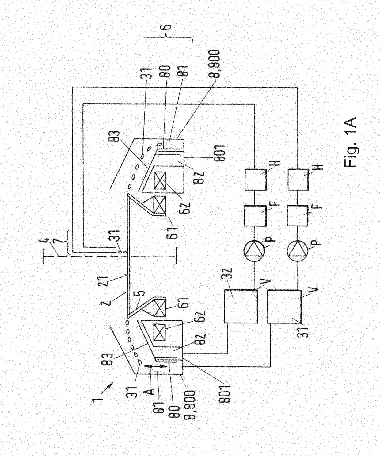
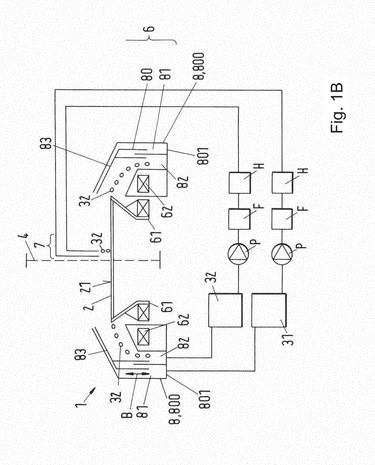
[0057]FIGS. 1A and 1B show in a schematic representation a treatment apparatus 1 in accordance with the invention having a bearingless motor 6. In this respect, FIG. 1A differs from FIG. 1B only in that in accordance with FIG. 1A the first treatment medium 32 is led into the first chamber 81 in a first workstep, whereas in FIG. 1A the first method step is already concluded and a second method step is shown in which an outflow of the second treatment medium 32 into the second chamber 82 is just being shown.

[0058]The specific embodiment of a treatment apparatus 1 in accordance with the invention for treating a surface 21 of a body 2 with a first treatment medium 31 and a second treatment medium 32 includes a holding device 5 rotatable about an axis of rotation 4 for receiving and holding the body 2 which in the present example is a wafer 2 for manufacturing microelectronic components. The treatment device 1 further includes a rotor 61 of the rotary drive 6, said rotor being rotational...

second embodiment

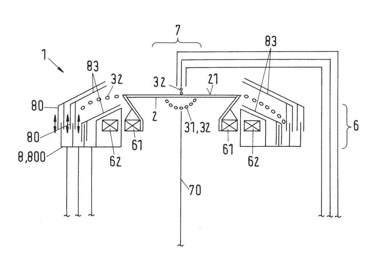
[0064]It is self-explanatory in this respect that the invention is not restricted to treatment apparatus 1 with which only two different treatment media 31, 32 can be separately collected. A second embodiment in accordance with FIG. 1A and FIG. 1B respectively having three chambers is thus shown schematically with reference to FIG. 2 with which three different treatment media can be separately collected. The skilled person immediately understands how the treatment chamber 1 is to be modified so that four or even more different treatment media can also be separately collected.

[0065]It is also possible, as already mentioned further above, that the wafer 2 has the treatment medium 31, 32 applied from both sides and is processed on both sides. This is possible in accordance with FIG. 2A in that an annular rotor 61 is used, wherein a further supply device 70, in addition to the supply device 7 which is above the wafer 2, is arranged beneath the wafer 2 on the oppositely disposed side. A ...


PUM


Abstract

The invention relates to a treatment apparatus (1) for treating a surface (21) of a body (2) with a first treatment medium (31) and a second treatment medium (32). In this respect, the treatment apparatus (1) includes a holding device (5) rotatable about an axis of rotation (4) for receiving and holding the body (2) and a rotary drive (6) rotationally fixedly coupled to the rotatable holding device (5) as well as a supply device (7) for supplying the first treatment medium (31) and the second treatment medium (32) to the surface (21) of the body (2) held in the holding device (5). The treatment apparatus includes a collection container (8) having a separation element (80) which separation element (80) divides the collection container (8) into a first chamber (81) and into a second chamber (82) such that the first treatment medium (31) can be collected in the first chamber (81) and the second treatment medium (32) can be collected separately in the second chamber (82). In accordance with the invention, the collection container (8) includes a base chamber part (800) not movable with respect to the holding device (5) and the separation element (80) is movably arranged between a first position (A) and a second position (B) such that the first treatment medium (31) can be led off into the first chamber (81) in the first position (A) and the second treatment medium (32) can be led off into the second chamber (82) in the second position (B).

Description

CROSS-REFERENCES TO RELATED APPLICATIONS[0001]This application is a continuation of U.S. patent application Ser. No. 13 / 045,437 filed Mar. 10, 2011, entitled “Treatment Apparatus for Treating a Surface of a Body,” which claims the priority of European Application No. 10 158 604.8, filed on Mar. 31, 2010, the disclosures of which are incorporated herein by reference.BACKGROUND OF THE INVENTION[0002]The invention relates to a treatment apparatus for treating a surface of a body, in particular for treating a wafer in accordance with the preamble of independent claim 1.[0003]There is a need in a number of industrial processes, for example in the manufacture of semiconductors and chips, to provide specific surfaces of substrates, for example wafers, for the manufacture of electronic components with suspensions in a controlled manner to process their surfaces. Chemical-mechanical planarization processes (CMP, cleaning and / or corroding of wafers or the removal of photoresist to be removed ...

Claims


Application Information

Patent Timeline
Patent Type & Authority Applications(United States)
IPC IPC(8): H01L21/67
CPCH01L21/67051H01L21/6708H01L21/6715H01L21/02282H01L21/02307H01L21/02343
Inventor SCHOEB, RETO
Owner LEVITRONIX
Why Eureka
Try Eureka