

Insect trapping unit and insect trap
- Summary
- Abstract
- Description
- Claims
- Application Information
AI Technical Summary
Benefits of technology
Problems solved by technology
Method used
Image

Examples
first embodiment
1. The First Embodiment
1. 1. Summary
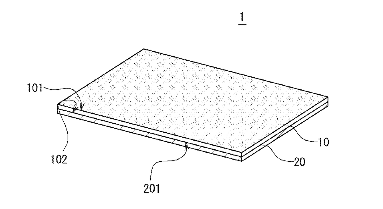
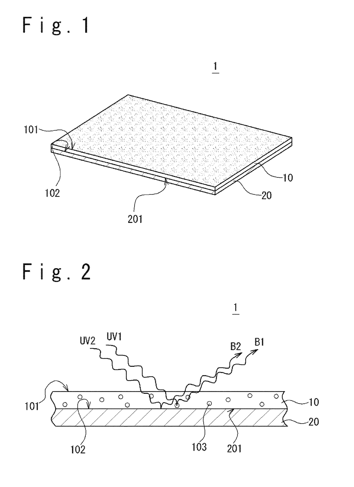
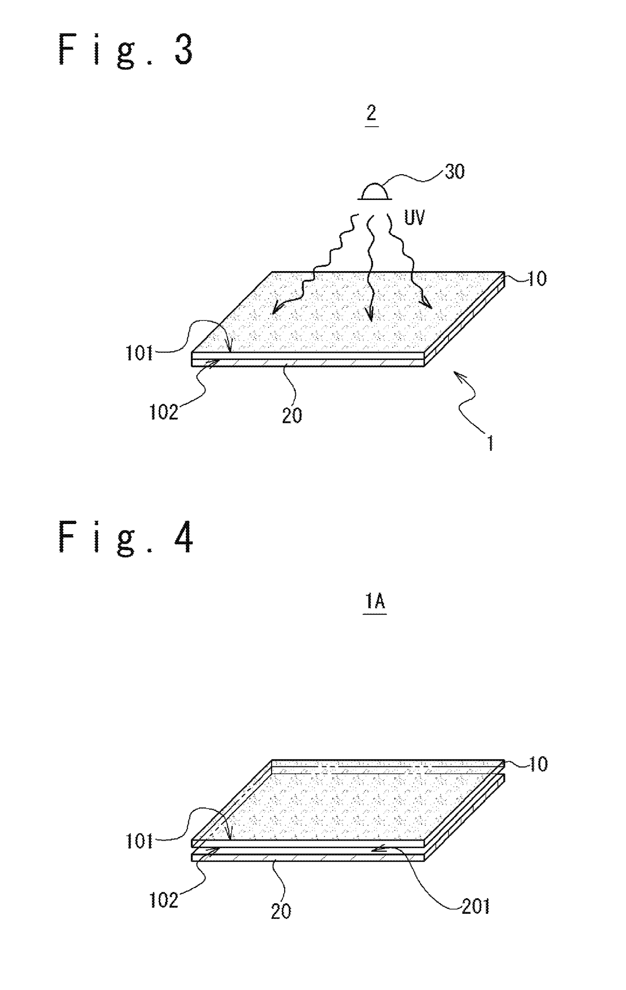
[0072]Flies are known to be attracted by, not only ultraviolet ray (e.g.: wave length equal to or more than 300 nm, and equal to or less than 400 nm), but also visible ray. It has been found that, among visible ray, blue ray (e.g.: wave length equal to or more than 400 nm, and equal to or less than 500 nm) are effective. By using blue ray in addition to ultraviolet ray, in addition to flies attracted by ultraviolet ray, flies attracted by blue ray also can be trapped too. That is, a band of wave length with which flies are trapped will become broader (e.g.: wave length equal to or more than 350 nm, and equal to or less than 500 nm). Therefore, the inventor of the present invention focused on widening the band of wave length with which flies are trapped and increasing illuminance of blue ray. Then, the inventor considered that, the more the blue ray illuminance is increased, in other word, the brighter the blue ray is, the more flies are easily tra...
second embodiment
2. Second Embodiment
[0110]An ultraviolet ray LED (Light Emitting Diode) with a high directivity may be used as the light source. FIG. 12 is an external view of an insect trap 2B.
[0111]The insect trap 2B has a first LED socket 311 and a second LED socket 312. The first LED socket 311 has a plurality of first ultraviolet ray LEDs 30b1. The first LED socket 311 is connected to a pair of first connectors 421. The second LED socket 312 has a plurality of second ultraviolet ray LEDs 30b2. The second LED socket 312 is connected to a pair of second connectors 422.
[0112]Each of the plurality of first ultraviolet ray LEDs 30b1 is arranged along the longitudinal direction of the first LED socket 311, at equal intervals. Similarly, each of the plurality of second ultraviolet ray LEDs 30b2 is arranged along the longitudinal direction of the second LED socket 312, at equal intervals, too. The number of the first ultraviolet ray LEDs 30b1 arranged to the first LED socket 311 may be arbitrary (e.g....
modified example
[0117]FIG. 14 is a schematic diagram showing a modified example of arrangement of an ultraviolet ray LED. FIG. 14 corresponds to a horizontal cross-sectional view by A-A shown in FIG. 12. The first LED socket 311 further has a plurality of third ultraviolet ray LEDs 30b3. Each of the plurality of third ultraviolet ray LEDs 30b3 irradiates ultraviolet ray upward the insect trap 2B. This irradiation direction is shown as L3. The second LED socket 312 further has a plurality of fourth ultraviolet ray LEDs 30b4. Each of the plurality of fourth ultraviolet ray LEDs 30b4 irradiates ultraviolet ray to the adhesive surface 101 of the adhesive sheet 10. This irradiation direction is shown as L4.
[0118]In this modification example can be obtained an effect in that the illuminance of blue ray can be maintained while maintaining enough illuminance of ultraviolet ray radiated outside the insect trap.
PUM
 Abstract
Description
Claims
Application Information