Balance shaft friction damper

a technology of friction damper and shaft, which is applied in the direction of shock absorbers, mechanical equipment, hoisting equipment, etc., can solve the problems of gear damage or damage to the rubber damper portion, and achieve the effect of preventing a torque reduction of the lip sliding surface and stably circulating the lubrican

Inactive Publication Date: 2017-10-12
NOK CORP
View PDF1 Cites 3 Cited by
  • Summary
  • Abstract
  • Description
  • Claims
  • Application Information

AI Technical Summary

Benefits of technology

[0022]According to the present invention, a balance shaft friction damper can be provided that is capable of preventing a torque reduction of a lip sliding surface while ensuring an axial flow path for a lubricant to stably circulate the lubricant.

Problems solved by technology

On the other hand, if the torque of the friction damper is insufficient due to degradation of rubber or the like, a problem will occur of damage to the rubber damper portion or damage to the gear portion.

Method used


Image

  • Balance shaft friction damper
  • Balance shaft friction damper
  • Balance shaft friction damper

Examples


Embodiment Construction

[0030]Now, an embodiment of a balance shaft friction damper (hereinafter, simply referred to as friction damper) according to the present invention will be described with reference to the drawings.

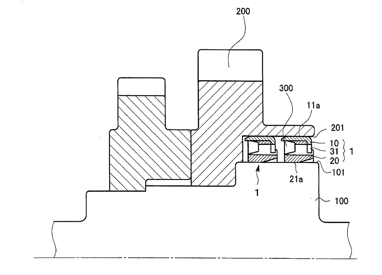
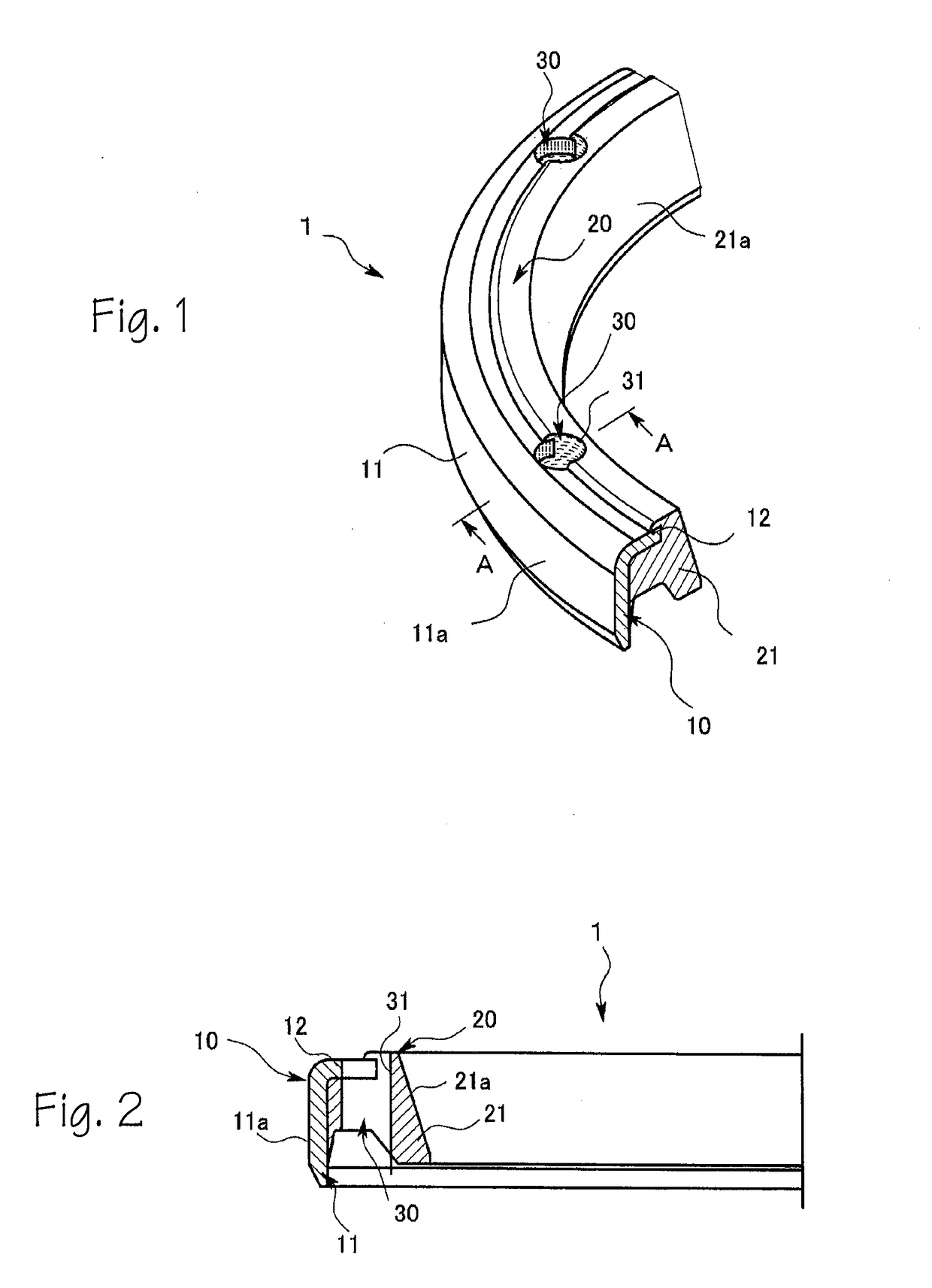
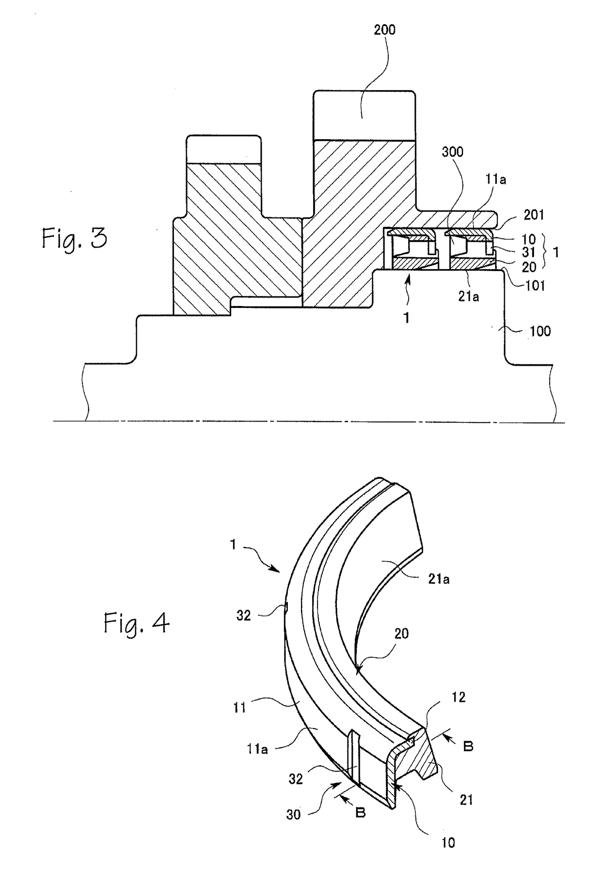
[0031]FIG. 1 is a partially fragmentary top illustration of an example of a friction damper according to the present invention, FIG. 2 is a sectional illustration taken along the line A-A in FIG. 1, and FIG. 3 is a partial sectional view of a balance shaft with the friction damper in FIGS. 1 and 2 being mounted.

[0032]A friction damper 1 shown in FIGS. 1 and 2 includes a metal mounting ring 10, and an annular elastic ring member 20 made of a rubber-like elastic material provided on an inner peripheral side of the mounting ring 10.

[0033]The mounting ring 10 is fabricated by, for example, press molding a metal plate such as a steel plate, and includes an axially extending cylindrical portion 11, and a flange portion 12 formed integrally with the cylindrical portion 11. The flange portion 12 i...


PUM

PropertyMeasurementUnit
pressureaaaaaaaaaa
rotation torqueaaaaaaaaaa
torqueaaaaaaaaaa

Abstract

The present invention has an object to provide a balance shaft friction damper (1) capable of preventing a torque reduction of a lip sliding surface while ensuring an axial flow path for a lubricant to stably circulate the lubricant. The object is achieved by a balance shaft friction damper (1) including: a metal mounting ring (10) that is mounted in an annular gap (300) between a shaft portion (100) of a balance shaft of an engine and a gear portion (200) provided on an outer periphery of the shaft portion (100), and has a fitting surface (11a) fitted and secured to one of an outer peripheral surface (101) of the shaft portion (100) and an inner peripheral surface (201) of the gear portion (200); and an annular elastic ring member (20) made of a rubber-like elastic material and provided on the mounting ring (10), and has a lip sliding surface (21a) brought into close contact with the other of the outer peripheral surface (101) of the shaft portion (100) and the inner peripheral surface (201) of the gear portion (200), wherein an oil flow path portion (30) that allows axial circulation of a lubricant is formed in a position across the mounting ring (10) and the elastic ring member (20) and apart from the lip sliding surface (21a), and / or an oil flow path portion (30) that allows axial circulation of a lubricant is formed in a position in the mounting ring (10) and apart from the lip sliding surface (21a).

Description

FIELD OF THE INVENTIONS[0001]The present invention relates to a balance shaft friction damper of an internal combustion engine, and more particularly to a balance shaft friction damper capable of maintaining high rotation torque without preventing circulation of a lubricant.BACKGROUND OF THE INVENTIONS[0002]A balance shaft friction damper of an internal combustion engine is a rubber part having high rotation torque that connects a shaft portion of a balance shaft for reducing vibration of a reciprocating engine, and a gear portion provided on an outer periphery of the shaft portion. The friction damper maintains high torque and thus absorbs vibration, and is also abruptly actuated to damp the torque when the shaft portion of the balance shaft oscillates with respect to the gear portion, thereby preventing damage to a rubber bumper portion for impact absorption provided on the gear portion.[0003]On the other hand, if the torque of the friction damper is insufficient due to degradatio...

Claims


Application Information

Patent Timeline
Patent Type & Authority Applications(United States)
IPC IPC(8): F16F15/129F16F7/04F16H55/14
CPCF16F15/129F16H55/14F16F2224/025F16F15/264F16F2230/04F16F7/04
Inventor ARAI, HIDENORI
Owner NOK CORP
Why Eureka
Try Eureka