Efficiently determining network topology

a network topology and network topology technology, applied in the field of network topology determination, can solve the problems of complex objectives and change in the network topology of multi-node systems

Active Publication Date: 2017-10-19
LENOVO GLOBAL TECH INT LTD
View PDF17 Cites 12 Cited by
  • Summary
  • Abstract
  • Description
  • Claims
  • Application Information

AI Technical Summary

Problems solved by technology

Furthermore, the network topology within a multi-node system may change over time as nodes are added, removed, or suffer a node failure or a connection failure.
This objective becomes complex as the number of nodes in the computing system increases.

Method used


Image

  • Efficiently determining network topology
  • Efficiently determining network topology
  • Efficiently determining network topology

Examples


Embodiment Construction

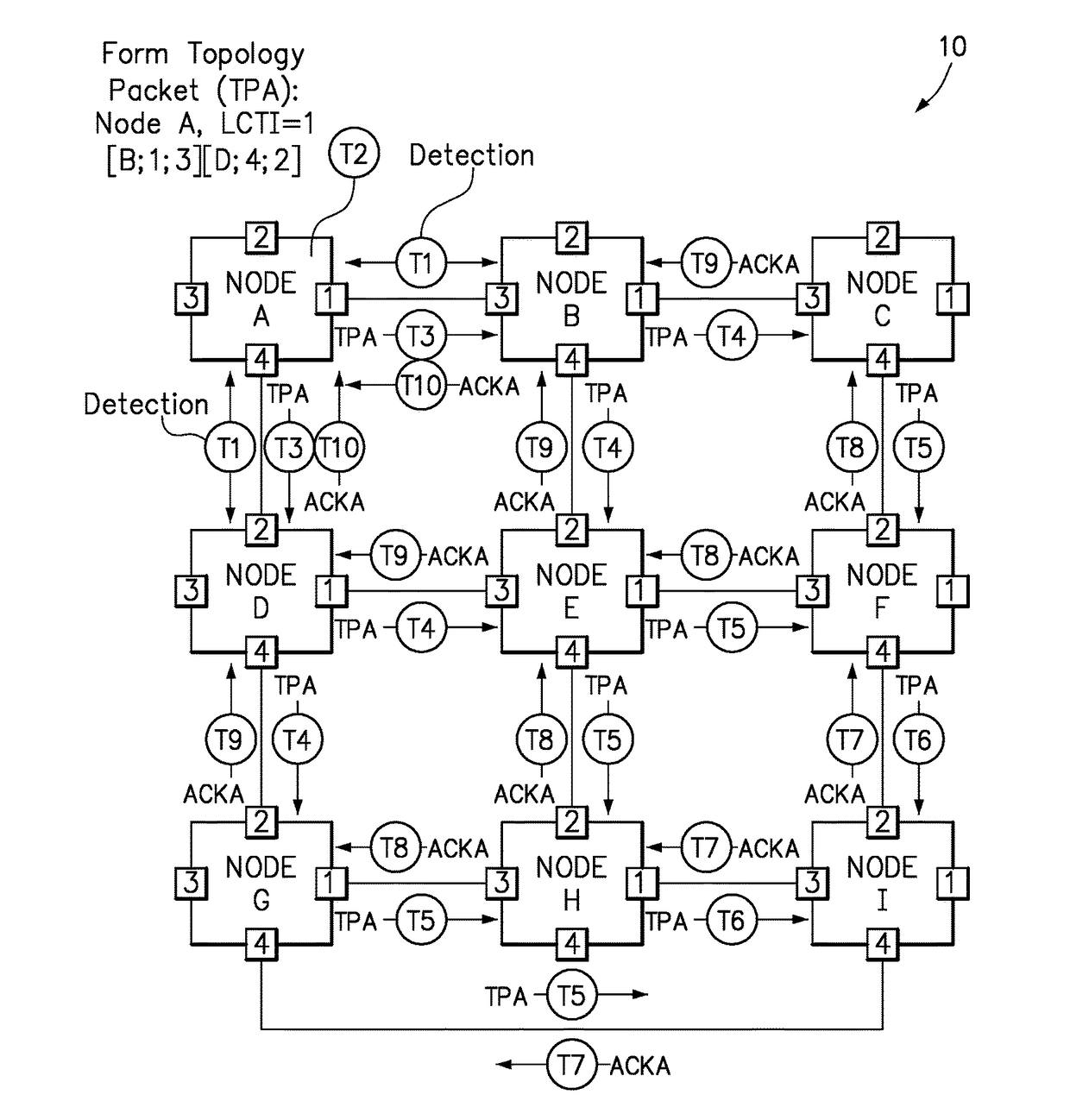
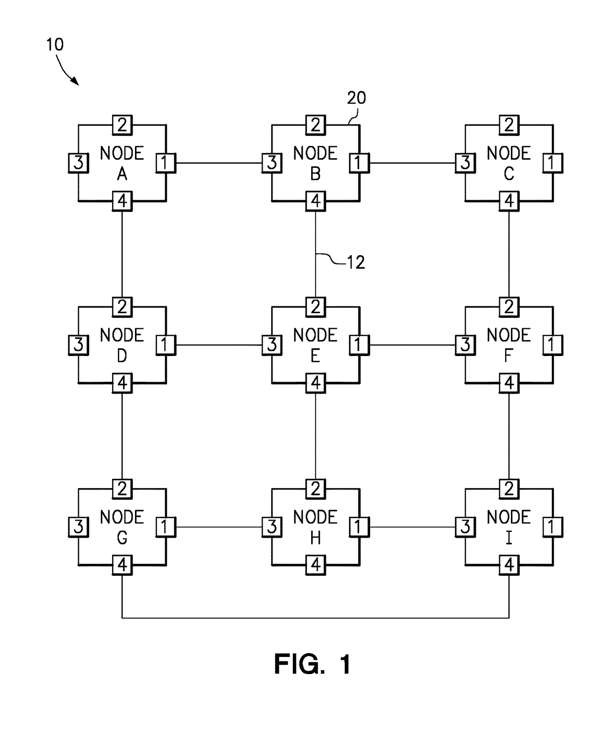
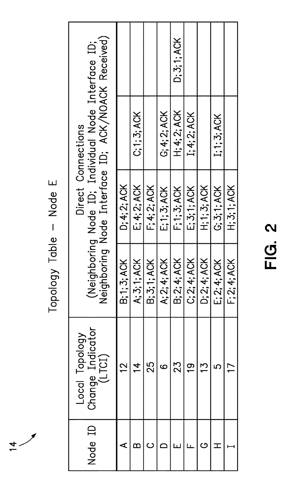
[0015]One embodiment of the present invention provides a method that enables an individual compute node in a multi-node system to detect a network topology of the multi-node system. The method comprises each individual node in the multi-node network detecting a connection for each neighboring node that is directly connected to one of a plurality of interfaces of the individual node and identifying the neighboring node and a neighboring node interface enabling the connection. The method further comprises each individual node storing a local topology change indicator that is incremented every time the individual node detects a change in any said connection. In addition, each individual node generates and sends an individual node topology packet over each connection with a neighboring node in response to detecting a change in any connection, wherein the individual node topology packet includes topology data identifying, for each connection between the individual node and a neighboring ...


PUM


Abstract

A method allows each individual node in the multi-node computing system to detect the topology of the computing system. Each individual node detects its own connections with neighboring nodes directly connected to the individual node, and sends out a topology packet on all of its interfaces with a local topology change indicator that increments with each topology packet sent out. Each individual node stores their own topology table with an entry for each node from which it has received a topology packet, including the local topology change number which enables the node to determine whether a received topology packet is more recent than data already stored in the topology table. Each node updates its topology table with new topology data, forwards new topology data, and sends back acknowledgements to a source node only upon receiving acknowledgements from all other nodes.

Description

BACKGROUNDField of the Invention[0001]The present invention relates to a method for determining the network topology of the computing system including a plurality of compute nodes.Background of the Related Art[0002]A multi-node system including a plurality of compute nodes may be configured in many different ways depending upon the various connections between compute nodes. For example, a network topology may form a linear topology, ring topology, start topology, a partially or fully connected mesh topology, or a hybrid topology. However, in order to maximize the efficiency of communication between nodes it is necessary for each of the nodes to have access to a description of the logical network topology within the multi-node system. For example, one of the individual compute nodes may communicate with another compute node over a direct connection rather than an indirect connection through one or more other compute nodes.[0003]Furthermore, the network topology within a multi-node sy...

Claims


Application Information

Patent Timeline
Patent Type & Authority Applications(United States)
IPC IPC(8): H04L12/24H04L45/02
CPCH04L41/12H04L45/021H04L45/28H04L45/02H04L41/00H04L61/00
Inventor IORGA, RADU MIHAICALCIU, CORNELIU-ILIE
Owner LENOVO GLOBAL TECH INT LTD
Why Eureka
Try Eureka