Optical lenses for laser marking

Active Publication Date: 2017-11-02
HANS LASER TECH IND GRP CO LTD
View PDF2 Cites 1 Cited by
  • Summary
  • Abstract
  • Description
  • Claims
  • Application Information

AI Technical Summary

Benefits of technology

The patent text describes an optical lens for laser marking that has both high engraving quality and speed. The lens uses a F-θ structure and ensures a fine and deep engraving line. It is more efficient than conventional engraving lenses. Thus, the technical effect of the patent text is to provide an optical lens for laser marking that engraves with high quality and efficiency.

Problems solved by technology

Although using a single engraving lens can improve the quality of the engraving line, the operating table is required to move back and forth to cooperate with the lens for engraving or cutting, such that the engraving speed is very slow.

Method used


Image

  • Optical lenses for laser marking
  • Optical lenses for laser marking
  • Optical lenses for laser marking

Examples


Embodiment Construction

[0017]In order to make the above and other objects, features and advantages of the present invention become more apparent, the specific embodiments will be described in detail in combination with the accompanying drawings. Numerous specific details are described hereinafter in order to facilitate a thorough understanding of the present disclosure. The various embodiments of the disclosure may, however, be embodied in many different forms and should not be construed as limited to the specific embodiments set forth hereinafter, and people skilled in the art can make similar modifications without departing from the spirit of the present disclosure.

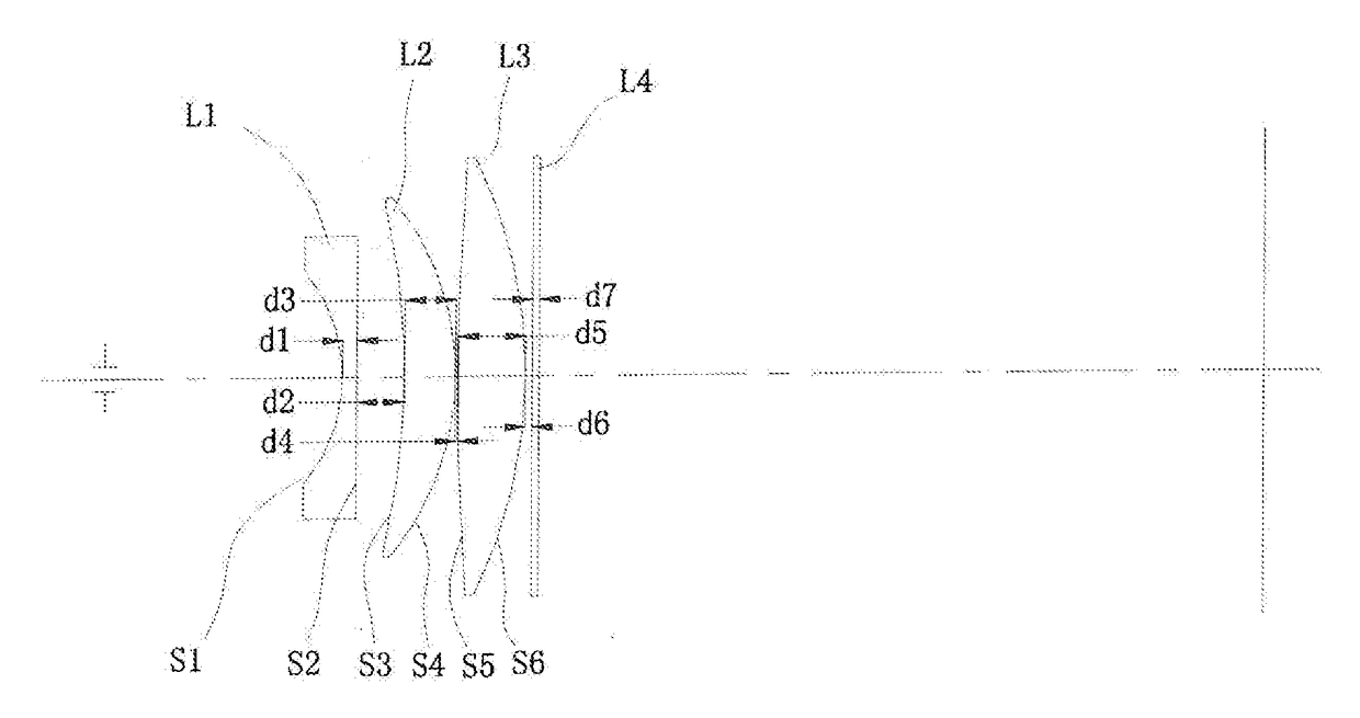
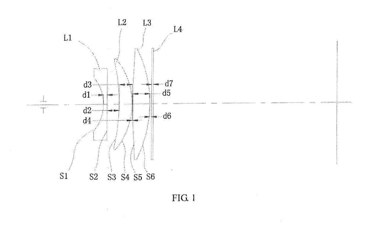
[0018]FIG. 1 is a schematic diagram of an optical lens for laser marking according to one embodiment, for illustrative purposes, only portions related to implementation of the disclosure are shown.

[0019]In an optical system of the illustrated embodiment, the propagation direction of the light is from the left side to the right side of the dra...


PUM

PropertyMeasurementUnit
Fractionaaaaaaaaaa
Thicknessaaaaaaaaaa
Wavelengthaaaaaaaaaa

Abstract

An optical lens for laser marking includes a first lens (L1), a second lens (L2), and a third lens (L3), which are successively coaxially arranged along a transmission direction of incident light, wherein the first lens (L1) and the second lens (L2) are meniscus lenses, and the third lens (L3) is a biconvex lens; wherein the first lens (L1) has a first surface (S1) and a second surface (S2), the second lens (L2) has a third surface (S3) and a fourth surface (S4), the third lens (L3) has a fifth surface (S5) and a sixth surface (S6); the first surface (S1) to the sixth surface (S6) are successively arranged along the transmission direction of the incident light; wherein radii of curvature of the first surface to the sixth surface are −47±5% mm, ∞, −218±5% mm, −81±5% mm, 778±5% mm, and −142±5% mm, respectively; wherein central thicknesses of the first lens, the second lens, and the third lens are 4±5% mm, 15±5% mm, and 18±5% mm, respectively. The optical lens for laser marking not only has high engraving quality, but also has a high engraving speed with a higher efficiency than conventional engraving lens.

Description

FIELD OF THE INVENTION[0001]The present disclosure relates to the field of optical lens, and more particularly relates to an optical lens for marking in a laser processing device.BACKGROUND OF THE INVENTION[0002]With the development of electronic devices such as mobile phones, personal computers and panel TVs, the production demand of panels applied to these products is also gradually increased. During the production process of the panels, it requires to scribe the panel with laser to engrave and cut the panels. In order to ensure that the panels meet technical requirements of these products, a “fine” and “deep” engraving line should be guaranteed during engraving the panels with laser. Therefore, requirements of the engraving lens for the laser marking machine are getting higher and higher.[0003]Conventional laser marking machine use a single engraving lens or a plurality of (usually up to three) engraving lenses. Although using a single engraving lens can improve the quality of th...

Claims


Application Information

Patent Timeline
IPC IPC(8): B23K26/06G02B13/00B23K26/18
CPCB23K26/0648B23K26/18G02B13/0035
Inventor SUN, BOLI, JIAYINGZHOU, CHAOMINGCHEN, YUQINGGAO, YUNFENG
Owner HANS LASER TECH IND GRP CO LTD
Why Eureka
Try Eureka