Electric-motor-assisted bicycle

a technology of electric motors and bicycles, applied in the direction of bicycles, bicycle equipment, transportation and packaging, etc., can solve the problems of difficult to tightly sandwich the drive unit between the side plates, and the side plates are difficult to deform sufficiently, so as to increase the attachment strength or connection force, increase the stiffness of the bracket, and high the effect of stiffness

Active Publication Date: 2017-11-02
YAMAHA MOTOR CO LTD
View PDF3 Cites 4 Cited by
  • Summary
  • Abstract
  • Description
  • Claims
  • Application Information

AI Technical Summary

Benefits of technology

[0007]The present inventors considered increasing a stiffness of the bracket on an electric-motor-assisted bicycle used under harsh conditions, such as racing, to increase an attachment strength or connecting force between the drive unit and the vehicle-body frame. However, for a bracket with very high stiffness, it is difficult to sufficiently deform the side p

Problems solved by technology

However, for a bracket with very high stiffness, it is difficult to sufficiently deform the si

Method used


Image

  • Electric-motor-assisted bicycle
  • Electric-motor-assisted bicycle
  • Electric-motor-assisted bicycle

Examples


Embodiment Construction

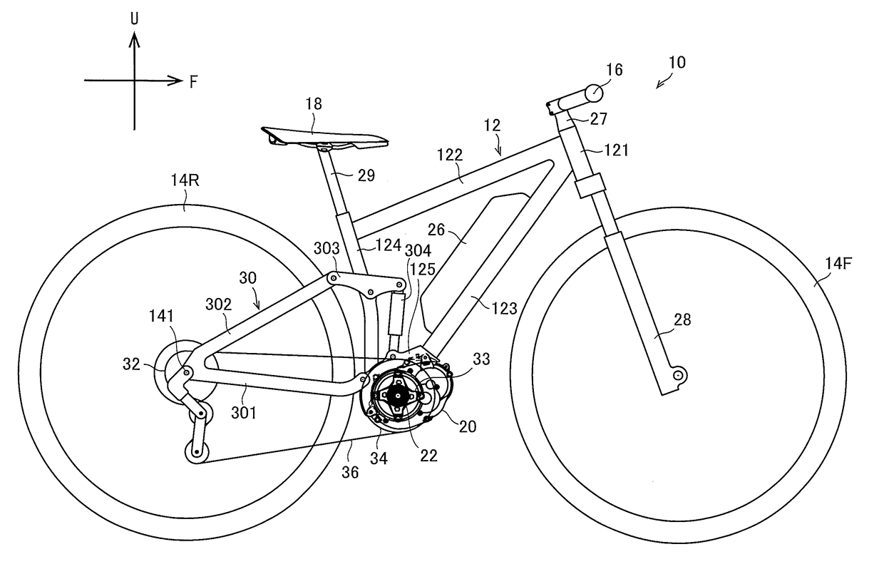
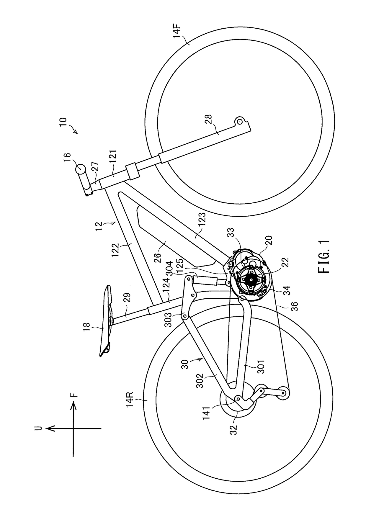
[0023]The present inventors researched and developed a structure that improves an attachment strength or connecting force between a drive unit and a vehicle-body frame.

[0024]The drive unit is attached to the vehicle-body frame via a bracket. A suspension boss of the drive unit is inserted between two side plates of the bracket, and a small gap is located between each side plate and the suspension boss.

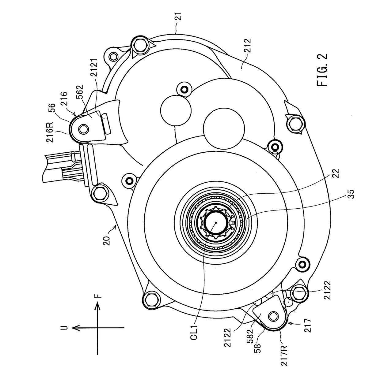
[0025]When such gaps are present and the drive unit is attached to the bracket, the drive unit is merely suspended by a bolt extending through the suspension boss. Thus, it is difficult to achieve a secure connection between the drive unit and the bracket.

[0026]To address this problem, the drive unit may be sandwiched between the side plates by the bolt and a nut to securely attach the drive unit to the bracket. For example, tightening forces of the bolt deform the side plates inwardly in the left-right direction of the vehicle by amounts of the gaps, and the side plates are closely at...


PUM


Abstract

A drive unit reliably and stably attached to a bracket, even if the bracket has high stiffness, includes a housing including first and second suspension bosses located between first and second side plates of the bracket in a left-right direction of a bicycle. A first bolt is fastened to the first suspension boss and inserted from an outside in the left-right direction of the bicycle into a hole in the first side plate. A cylindrical member is fitted into an insertion hole in the second suspension boss that is open toward the second side plate. The cylindrical member is slidable in the left-right direction of the bicycle and includes a thread groove located on an inner periphery thereof engaging a thread located on an outer periphery of a second bolt that is inserted from the outside in the left-right direction of the bicycle into a hole in the second side plate.

Description

CROSS REFERENCE TO RELATED APPLICATIONS[0001]This application claims the benefit of priority to Japanese Patent Application No. 2016-091470 filed on Apr. 28, 2016. The entire contents of this application are hereby incorporated herein by reference.BACKGROUND OF THE INVENTION1. Field of the Invention[0002]The present invention relates to electric-motor-assisted bicycles, and more particularly to electric-motor-assisted bicycles including a drive unit attached to a vehicle-body frame.2. Description of the Related Art[0003]Bicycles are used by many people, regardless of age and gender, as a handy transportation means. In recent years, electric-motor-assisted bicycles that add motor driving forces to rider pedaling forces to assist the rider have become popular. Such an electric-motor-assisted bicycle is disclosed in JP 2000-62679 A, for example.[0004]JP 2000-62679 A describes an electric-motor-assisted bicycle that includes a drive unit. The drive unit includes a crank axle. Pedals are...

Claims


Application Information

Patent Timeline
IPC IPC(8): F16B5/02B62M6/55B62K11/04B62M6/45B62M9/121B62M6/90
CPCF16B5/0225B62K11/04B62M9/121B62M6/90B62M6/55B62M6/45B62K25/02B62K25/286B62K25/30B62K19/34F16B5/0233
Inventor MANO, YASUNORI
Owner YAMAHA MOTOR CO LTD
Why Eureka
Try Eureka