Increasing the demand reduction effectiveness of an energy storage system

a technology of energy storage and demand reduction, applied in the field of energy storage systems, can solve the problems of not being able to effectively manage the average kw demand, incurring steep costs for utilities to deploy and maintain enough equipment, and significantly increasing electricity costs for customers, so as to reduce demand charges and effectively mitigate power limited events. , the effect of energy storage devices

Active Publication Date: 2017-11-16
STEM
View PDF8 Cites 2 Cited by
  • Summary
  • Abstract
  • Description
  • Claims
  • Application Information

AI Technical Summary

Benefits of technology

[0010]At least one advantage of the disclosed techniques is that the operation of the energy storage device is optimized to reduce demand charges. Notably, preemptively discharging the energy storage device during a first portion of the utility measurement interval enables the energy storage system to effectively mitigate a power limited event over the entire utility measurement interval irrespective of when the power limited event occurs. Consequently, the demand charges for the entire billing cycle may be reduced,

Problems solved by technology

Because utility companies do not store electricity for later use by customers, utility companies incur steep costs to deploy and maintain enough equipment to satisfy customer demand during demand peaks.
As is well-understood, such demand charges can lead to significantly higher electricity costs for customers.
One limitation of conventional system controllers is that they typically are unable to effectively manage average kW demand during a UMI when a “power limited event” occurs.
A power limited event is when the customer load exceeds the capability of the energy storage device(s) to prevent the net load from exceeding the set-point during a given UMI.
During UMIs that include power limited events, conventional system controllers may be unable to maintain the average kW demand of the UMI below the desired level.
Thus, power limited events can oftentimes lead to unacceptably high demand charges that significantly impact the total cost of energy during a billing cycle.
However, because there is only 5 minutes remaining in the UMI, there is not enough time left in the UMI to discharge the energy storage device long enough to limit the maximum average kW demand as measured by the utility company to 50 kW.

Method used


Image

  • Increasing the demand reduction effectiveness of an energy storage system
  • Increasing the demand reduction effectiveness of an energy storage system
  • Increasing the demand reduction effectiveness of an energy storage system

Examples


Embodiment Construction

[0022]In the following description, numerous specific details are set forth to provide a more thorough understanding of the present invention. However, it will be apparent to one of skilled in the art that the present invention may be practiced without one or more of these specific details. To facilitate understanding, identical reference numerals have been used, where possible, to designate identical elements that are common to the figures. It is contemplated that elements disclosed in one embodiment may be beneficially utilized on other embodiments without specific recitation. The drawings referred to here should not be understood as being drawn to scale unless specifically noted. Also, the drawings are often simplified and details or components omitted for clarity of presentation and explanation.

Overview of Distributed Energy Storage Systems

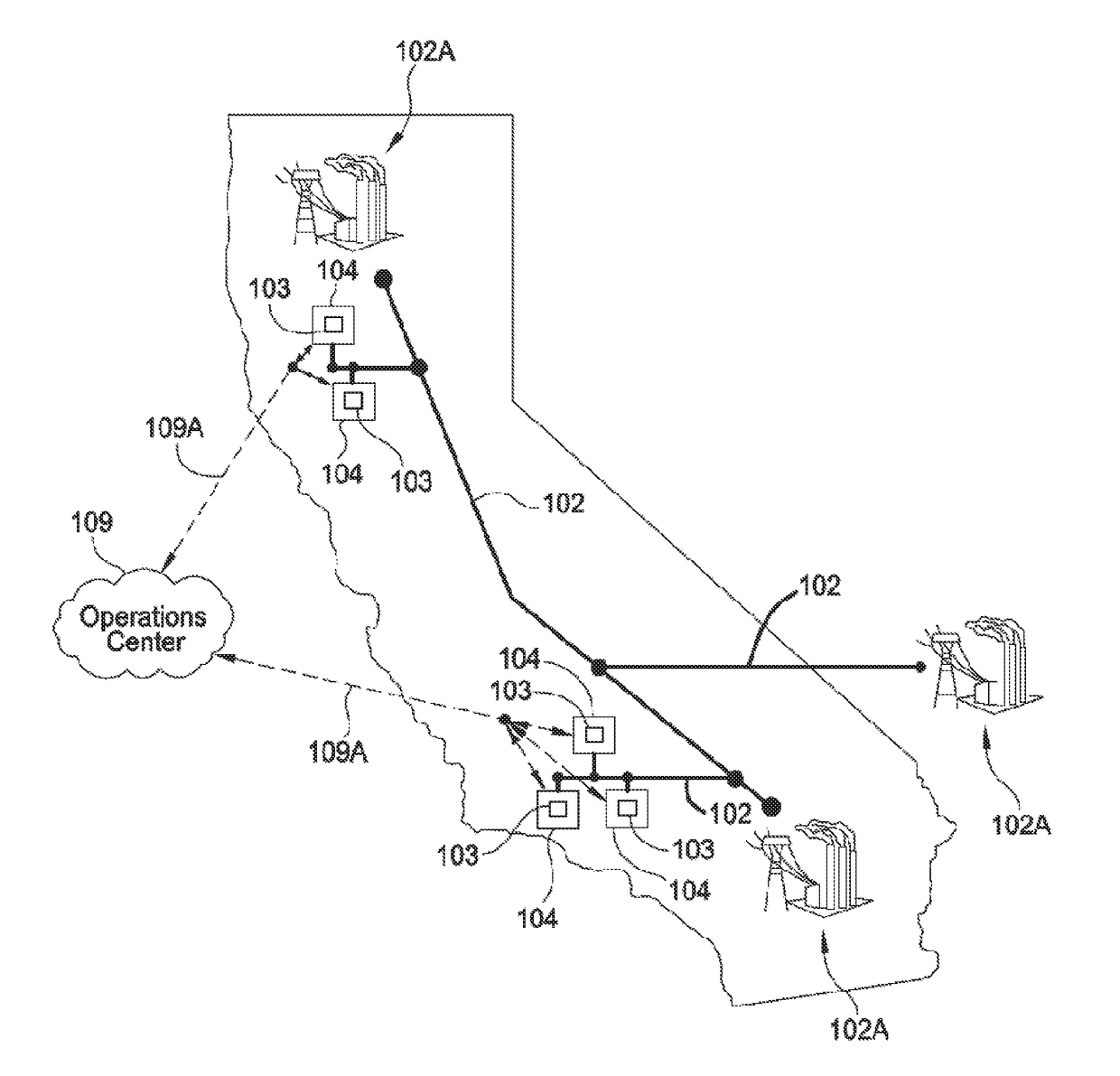
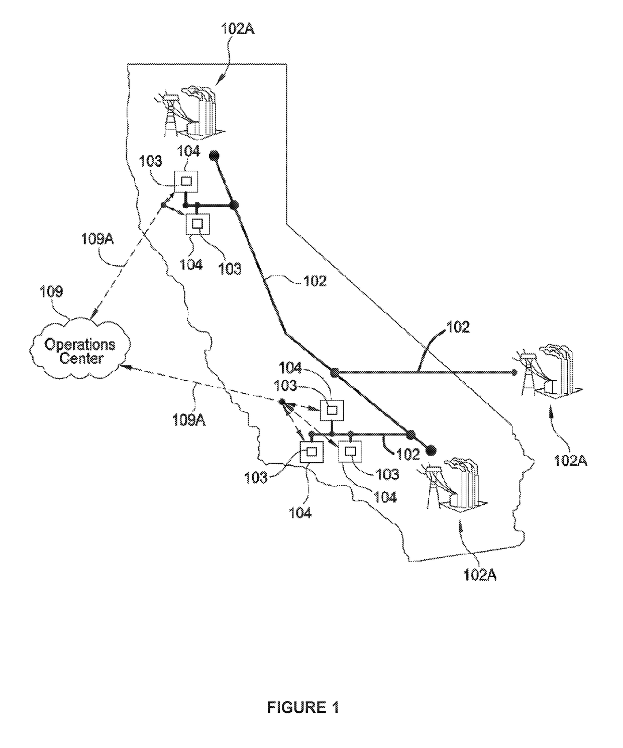
[0023]FIG. 1 is a conceptual illustration of multiple distributed energy storage systems 103 that are positioned at different electric load l...


PUM


Abstract

In various embodiments, a hedge mode plugin increases the ability of an energy storage system to reduce the demand charges associated with purchasing electricity from a utility. A utility measurement interval (UMI) is divided into a pre-discharge phase and a subsequent compensatory charge phase. During the pre-discharge phase, the hedge mode plugin causes an energy storage device to discharge. At the beginning of the compensatory charge phase, the hedge mode plugin computes time-indexed charge values based on the total amount of energy that the energy storage device discharged during the pre-discharge phase. The hedge mode plugin then causes the energy storage device to charge based on at least one of the charge values. By systematically pre-discharging and re-charging the energy device, the hedge mode plugin optimizes the demand reduction effectiveness of the energy storage system during each UMI while stabilizing the state-of-charge of the energy storage device across multiple UMIs.

Description

CROSS-REFERENCE TO RELATED APPLICATIONS[0001]Num This application claims the benefit of U.S. Provisional Patent Application Ser. No. 62 / 336,517 (Attorney Docket Number STEM / 0021USL) and filed on May 13, 2016. The subject matter of this related application is herein incorporated by reference.BACKGROUND OF THE INVENTIONField of the Invention[0002]Embodiments of the present invention generally relate to energy storage systems and, more specifically, to increasing the demand reduction effectiveness of energy storage systems.Description of the Related Art[0003]As is well-known, utility companies typically generate electricity on-demand. Because utility companies do not store electricity for later use by customers, utility companies incur steep costs to deploy and maintain enough equipment to satisfy customer demand during demand peaks. Consequently, utility companies typically charge relatively large customers (e.g., commercial or industrial customers) an additional “demand” charge durin...

Claims


Application Information

Patent Timeline
Patent Type & Authority Applications(United States)
IPC IPC(8): G05F1/66G05B11/01G05B19/042H02J5/00
CPCG05F1/66H02J5/00G05B19/042G05B11/01G05B2219/24136H02J3/32G05B15/02H02J3/28
Inventor BURLINSON, JONBENJAMIN, CHRISKEARNS, BENVENN, GARRISON
Owner STEM
Why Eureka
Try Eureka