Lifting platform

a platform and platform technology, applied in the field of platform lifting structure, can solve the problems of not being able to apply in the lifting table structure, the push force cannot be timely adjusted, and the inconvenience of use cannot be reduced, so as to achieve stable and labor-saving operation mechanism, effective reduction of the required force of operation

Inactive Publication Date: 2017-11-30
KELLY INT CORP
View PDF16 Cites 19 Cited by
  • Summary
  • Abstract
  • Description
  • Claims
  • Application Information

AI Technical Summary

Benefits of technology

[0005]The object of the present invention is to provide a lifting platform, wherein a movable support frame is set between a pre-set bearing platform and a base, the movable support frame is composed of a first and a second frames with their middle sections being cross and pivoted to each other, a damping extension element provided for being control to extend is set between the first and the second frames. By the property of the damping extension element that an equivalent pushing force (extension force) is released as a supporting force for balancing bearing weight of the bearing platform when the damping extension element is unlocked and stop positioning when it is locked, the required force of operation may be reduced effectively. Also, the first and the second frames are provided to support the bearing platform, so the first and the second frames could form a stable support in the processing of changing the cross angle with the lifting height of the bearing platform, to thereby provide a stable and labor-saving operation mechanism of lifting a bearing platform.

Problems solved by technology

However, the structure is a mechanism with only one single shaft for supporting, the supporting effect may not be achieved if the bearing area is too large, thus, it could not be applied in lifting table structure.
For example, in the existing lifting tables, the pneumatic device applies a fixed amount of pushing force (extension force), the pushing force could not be adjusted timely.
Thus, when a user wants to adjust its height, the user needs to force it down hard to lower the height if the bearing weight is smaller, the user needs to lift it up to raise the height if the bearing weight is too large, the inconvenience of use could not be reduced.
However, in practical application of the structure, since two ends of the first and the second bracing rods are respectively engaged with the same side of the table and the base, force may be concentrated to the ends of the first and the second bracing rods sliding on the bottom side of the table and the base in the process of adjusting the table up and down, so that the table may be easily shaken and the overall stability may be affected.

Method used


Image

  • Lifting platform
  • Lifting platform
  • Lifting platform

Examples


Embodiment Construction

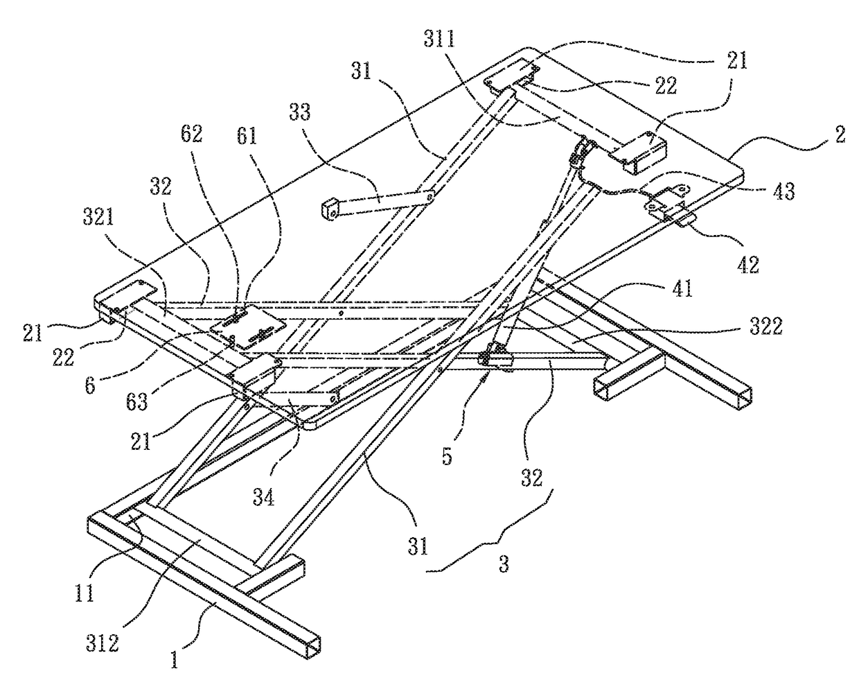
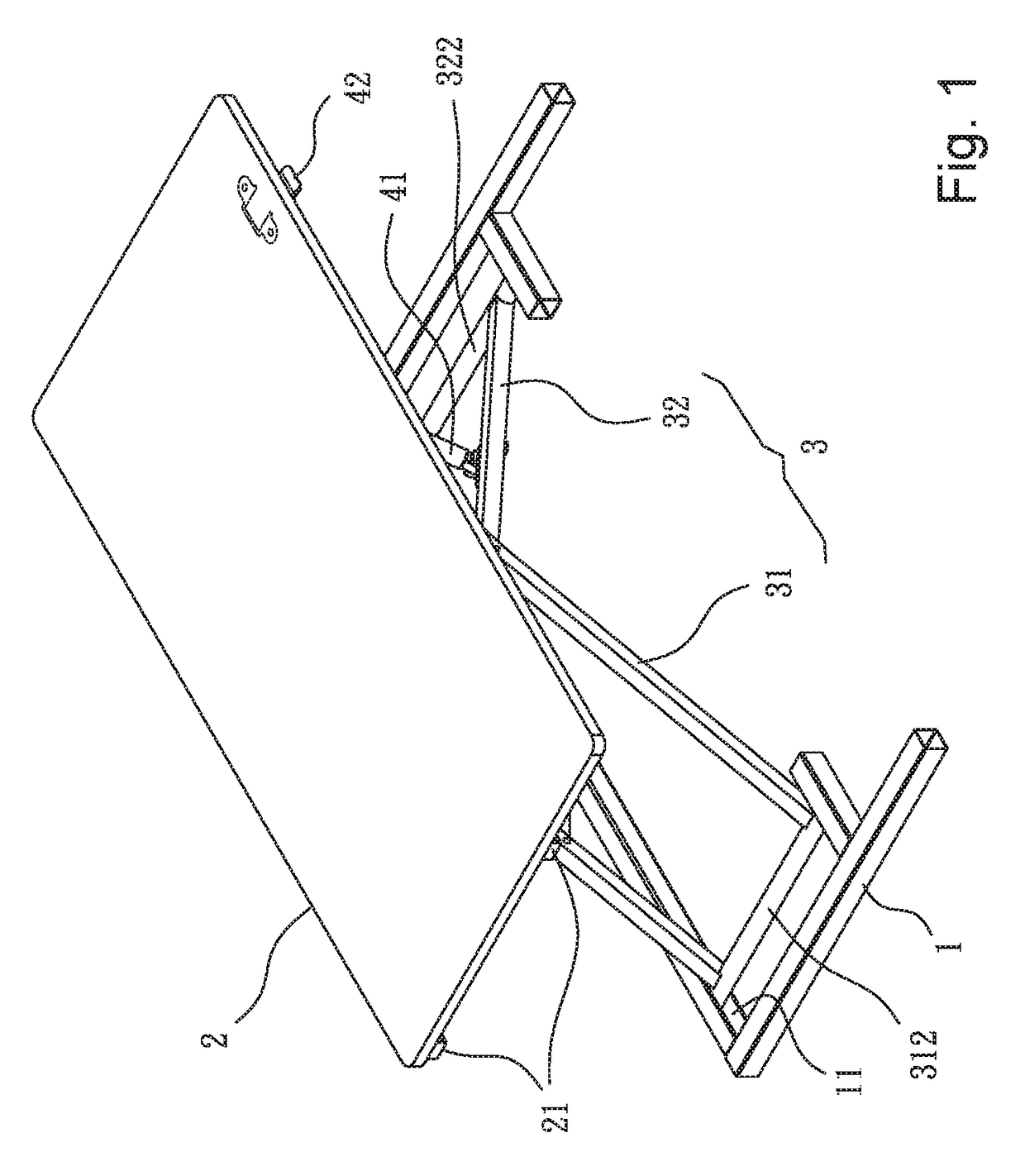
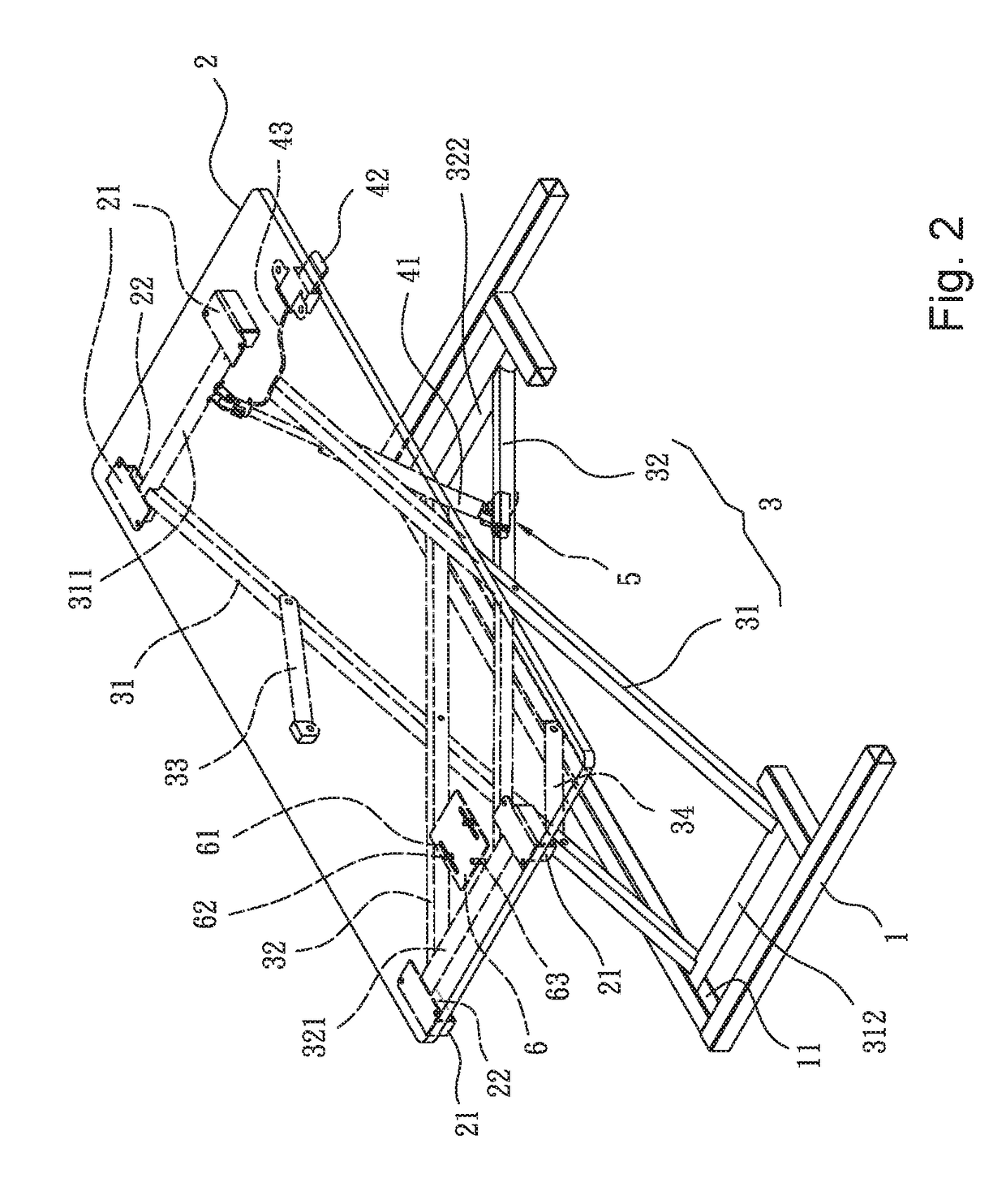
[0029]Please refer to FIG. 1 to FIG. 3, the first embodiment of the present invention includes: a base 1, a bearing platform 2, a movable support frame 3 and a damping mechanism 4, wherein lower guide grooves 11 parallel and symmetrical to each other are set on two sides of two ends of the base 1.

[0030]A top side of the bearing platform 2 is a surface for supporting objects, slide seats 21 parallel and symmetrical to each other are set on two sides of two ends of a bottom side of the bearing platform 2, each of the slide seat 21 includes an upper guide groove 22 extendedly parallel to each other on relative side.

[0031]The movable support frame 3 is composed of a first frame and a second frame with their middle sections being cross and pivoted to each other. In practice, there are various compositions of the first frame and the second frame, such as I-shaped bracket composed of a bracing rod and two cross rods, or a H-shaped bracket composed of two bracing rods and a cross rod, or th...


PUM


Abstract

A lifting platform, includes a movable support frame composed of a first and a second frames being cross pivotally and slidably connect between a bearing platform and a base, at least a positioning connecting rod set between the movable support frame and a portion close to the middle of the bearing platform or the base, and a damping extension element combine with an adjustment element and mounted on the movable support frame between the bearing platform and the base; the damping extension element controlled with extension or locking for adjusting the cross angle of the movable support frame, the adjustment element is provided to adjust the position of the damping extension element to form different supporting force to balance difference of bearing weight of the bearing platform, to achieve the effect of reducing the force required to operate the bearing platform for lifting.

Description

BACKGROUND OF THE INVENTION1. Field of the Invention[0001]The present invention relates to a platform lifting structure and, more particularly, to a lifting platform with centered support center of gravity and stable bearing capacity, which is provided to easily operate for lifting and stop positioning.2. Description of Related Art[0002]A conventional lifting mechanism for easily operating to adjust the height and position, simple ones, such as a common office pneumatic chair structure, wherein a chair is set on a bracket with wheels through an extension pneumatic device, and the pneumatic device is provided to operate by a control switch to fasten its extension position if locked and release extension force (it is usually not greater than human body weight) outwards if unlocked; if the force is greater than bearing weight, it could be extended continuously, so that the chair may be raised; if the force is smaller than bearing weight, it could be contracted, so that the chair could ...

Claims


Application Information

Patent Timeline
Patent Type & Authority Applications(United States)
IPC IPC(8): A47B9/16A47B21/02B66F7/06B66F7/08
CPCA47B9/16A47B21/02B66F7/085B66F7/065
Inventor CHUANG, MIN-LON
Owner KELLY INT CORP
Why Eureka
Try Eureka