Supply Device for a Molding Device, Molding Line and Method for Controlling Said Molding Line

a technology of supply device and supply device, which is applied in the field of polymerization, can solve the problems of significant loss of molding material, complex and expensive existing supply device, and difficulty in ensuring the safety of molding material, so as to reduce the quantity of cleaning solvent used

Active Publication Date: 2017-12-07
ESSILOR INT CIE GEN DOPTIQUE
View PDF2 Cites 2 Cited by
  • Summary
  • Abstract
  • Description
  • Claims
  • Application Information

AI Technical Summary

Benefits of technology

[0039]Thus, according to the invention, that part of the molding line that is situated upstream of the mixing device or of the supply device is not soiled by the polymerizable mixture. This makes it possible to significantly reduce the quantity of cleaning solvent used.
[0040]Moreover, the quantity of polymerizable mixture output by the molding device is adapted to the filling of the molds, thereby making it possible to make savings with regard to the quantities of reactants used; a smaller quantity of reactants is lost from the containers when cleaning is necessary.

Problems solved by technology

In order to simultaneously supply several molds of a molding device from a single supply device, notably with a reactive polymerizable mixture, a person skilled in the art is faced with various problems.
One major problem consists in ensuring that all of the molds are supplied satisfactorily under stable conditions, these conditions depending, inter alia, on the pressure at the inlet of the molding device, on the pressure at the inlet of the molds, on the supply volume, or on the viscosity of the mixture received by the molds, notably in the case of a reactive polymerizable mixture.
However, the existing supply devices are frequently complex and expensive since they provide individual commands relating to each of the molds of the molding device.
Moreover, in the prior art molding devices, the stability of supply, when it is obtained, is associated with a significant loss of molding material.

Method used


Image

  • Supply Device for a Molding Device, Molding Line and Method for Controlling Said Molding Line
  • Supply Device for a Molding Device, Molding Line and Method for Controlling Said Molding Line
  • Supply Device for a Molding Device, Molding Line and Method for Controlling Said Molding Line

Examples


Embodiment Construction

[0044]The description which follows with reference to the appended drawings, which are given by way of nonlimiting examples, will make it easy to understand what the invention consists of and and how it can be achieved.

[0045]In the appended drawings:

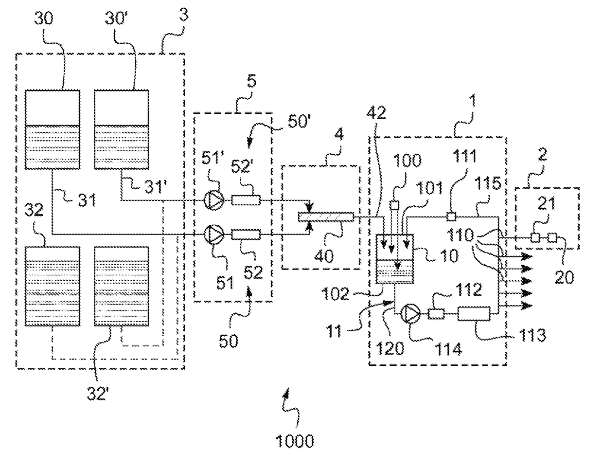
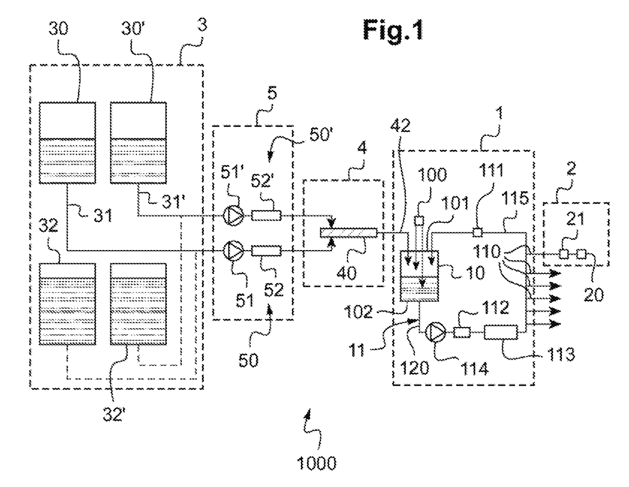
[0046]FIG. 1 schematically shows a molding line according to the invention; and

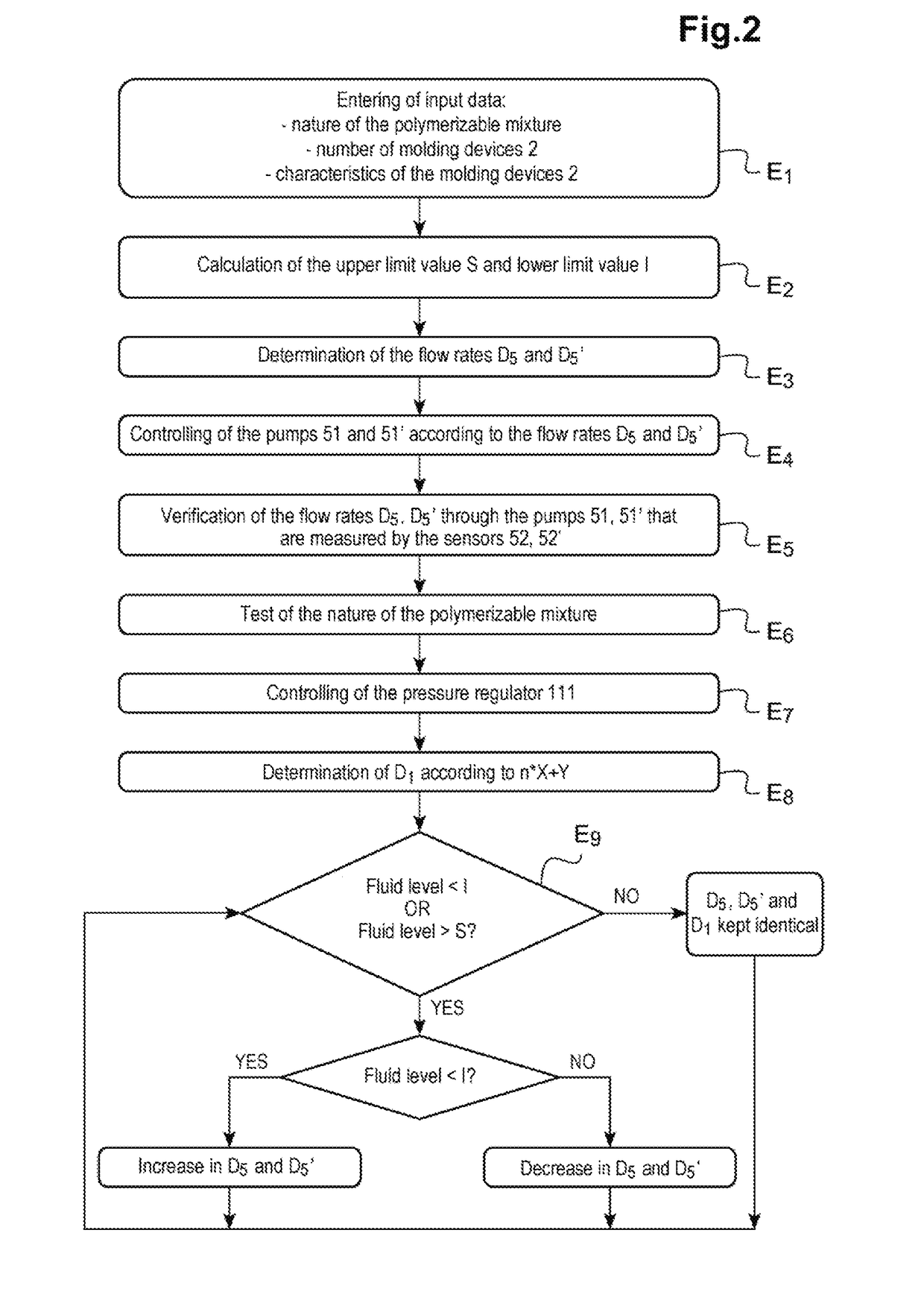
[0047]FIG. 2 is a flowchart representing the steps in a method for controlling the molding line schematically shown in FIG. 1.

[0048]In the rest of the description, the terms “upstream” and “downstream” will be used in the direction of fluid flow, in order to situate various elements with respect to one another in the supply device, or, more generally, in the molding line.

[0049]Similarly, the terms “inlet” and “outlet” will be used in the direction of fluid flow in order to describe the direction of mounting of the elements contained in the supply device, or more generally in the molding line.

[0050]A reactive polymerizable mixture is understood to be a mixture ...


PUM

PropertyMeasurementUnit
moldingaaaaaaaaaa
pressureaaaaaaaaaa
flow rateaaaaaaaaaa

Abstract

The invention relates to a device (1) for supplying at least one molding device (2) with a polymerizable mixture of at least two reactants.
According to the invention, said supply device comprises: a buffer tank (10) suitable for receiving said polymerizable mixture via an inlet (101) of said buffer tank, a supply circuit (11), looped with said buffer tank, to convey the polymerizable mixture to an inlet (110) of said at least one molding device and including, beyond said inlet of the molding device, a return pipe (115) connected to the inlet of the buffer tank for sending a portion of the polymerizable mixture from said return pipe, and a filling pipe (42) of said buffer tank, connected to said inlet of said buffer tank, separate from the return pipe, wherein said buffer tank is also suitable for receiving said polymerizable mixture or at least one of said reactants from said filling pipe.

Description

TECHNICAL FIELD OF THE INVENTION[0001]The present invention relates in a general manner to the field of the molding of polymerizable, notably reactive, mixtures.[0002]It relates in particular to a supply device for supplying at least one molding device with a polymerizable mixture comprising at least two reactants.[0003]It also relates to a molding line comprising, in fluidic communication from upstream to downstream in the direction of fluid flow, a reactant dispensing device, a device for mixing said reactants so as to obtain a polymerizable mixture, and a supply device.[0004]Finally, it relates to a method for controlling such a molding line.[0005]It finds particularly advantageous, but not exclusive, application for the manufacturing of transparent optical articles such as optical, in particular ophthalmic, blanks and lenses, and notably blanks of lenses for spectacles and sunglasses or vision correcting spectacles.TECHNOLOGICAL BACKGROUND[0006]In order to simultaneously supply ...

Claims


Application Information

Patent Timeline
Patent Type & Authority Applications(United States)
IPC IPC(8): B29C45/77B29D11/00B29C45/18B29K105/00
CPCB29C45/77B29D11/00432B29C45/1808B29C45/1866B29C2945/76832B29K2105/0002B29C2945/76056B29C2945/76545B29C2045/1891B29C31/04B29C31/06B29C39/006B29C39/24
Inventor VEQUE, ERICGENTILS, HERVE
Owner ESSILOR INT CIE GEN DOPTIQUE
Why Eureka
Try Eureka