Length-adjustable film applicator

Inactive Publication Date: 2018-01-04
HUANG YU CHUN
View PDF0 Cites 4 Cited by
  • Summary
  • Abstract
  • Description
  • Claims
  • Application Information

AI Technical Summary

Benefits of technology

The present invention provides a film applicator that can be adjusted based on the width of the film being used, reducing cost and making it easier to operate. The adjustment ring can be moved to secure the inner tube in place, allowing the user to adjust its length without driving the inner tube into rotation. This design allows for quicker and more convenient use of the film applicator.

Problems solved by technology

As a result, rotating shafts of various lengths must be kept at hand in order to work with films of different widths respectively, which is inconvenient.
In addition, replacing the rotating shaft is no easy task because the shaft must be dismounted in its entirety.

Method used


Image

  • Length-adjustable film applicator
  • Length-adjustable film applicator
  • Length-adjustable film applicator

Examples


Embodiment Construction

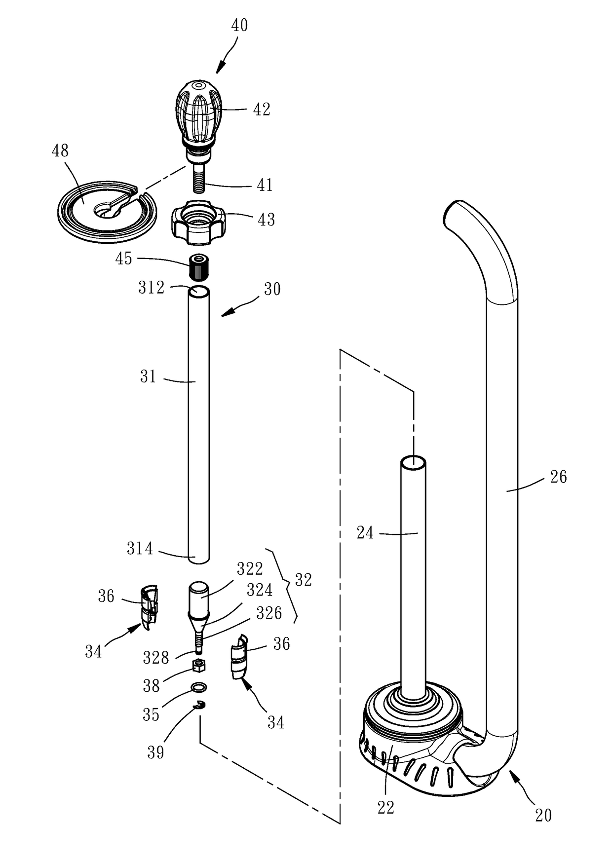
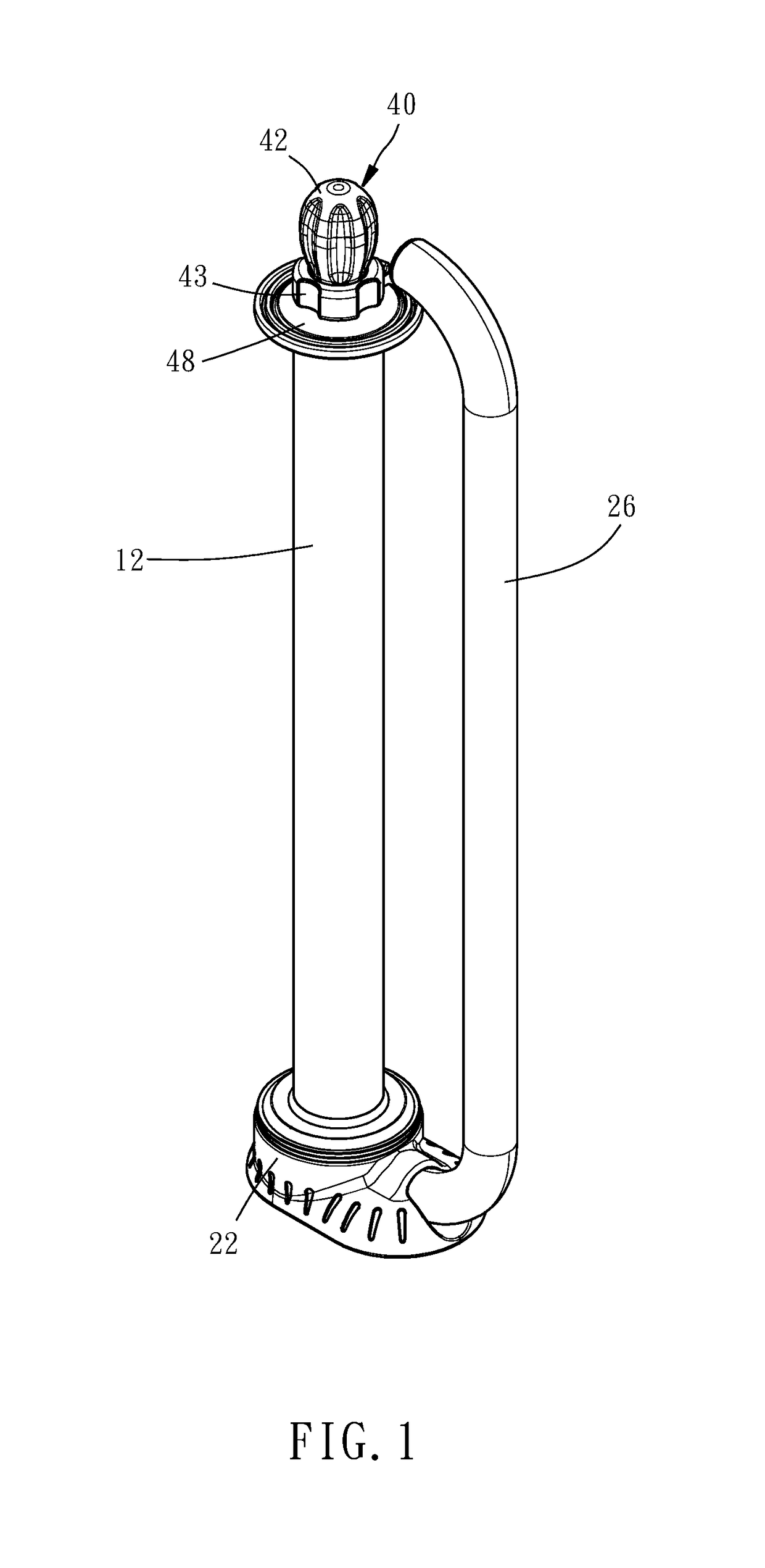
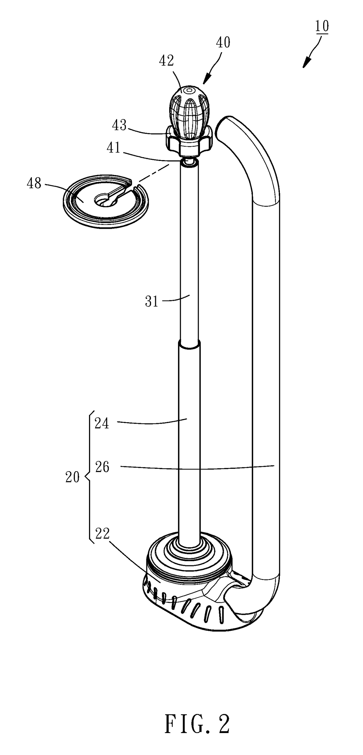
[0017]Referring to FIG. 1 to FIG. 3, the film applicator 10 according to an embodiment of the present invention includes a stand 20, an inner tube assembly 30, and an adjustment assembly 40.

[0018]The stand 20 has a supporting base 22, an outer tube 24, and a handle 26. The supporting base 22 is configured to support the bottom end of a roll of film 12. The outer tube 24 has one end fixed at the top side of the supporting base 22 and is so configured that the roll of film 12 can be mounted around the outer tube 24. The handle 26 has one end fixed at a peripheral portion of the supporting base 22 and is configured to be held with both hands.

[0019]As shown in FIG. 3 to FIG. 5, the inner tube assembly 30 has an inner tube 31, a positioning column 32, and a positioning sleeve 33. The inner tube 31 is provided in the outer tube 24 of the stand 20 in a rotatable and axially displaceable manner and is so configured that the roll of film 12 can be mounted around the inner tube 31, too. The i...


PUM

PropertyMeasurementUnit
Lengthaaaaaaaaaa

Abstract

A film applicator includes an outer tube, an inner tube in the outer tube, and an adjustment assembly in the inner tube. The adjustment assembly has a threaded shaft fixed in the inner tube, a retaining nut mounted around the threaded shaft, a turning knob rotatably mounted around the threaded shaft, and an adjustment ring threadedly provided around the threaded shaft. When at a first position, the adjustment ring pushes the turning knob against the retaining nut and allowing the threaded shaft to rotate the inner tube with respect to the outer tube, thereby adjusting the exposed length of and securing the inner tube. When at a second position, the adjustment ring does not push the turning knob, which therefore cannot drive the inner tube into rotation. The inner tube thus stays at the secured position.

Description

BACKGROUND OF THE INVENTION1. Technical Field[0001]The present invention relates to a film applicator and more particularly to a film applicator whose length is adjustable.2. Description of Related Art[0002]A film applicator is typically used to enhance the efficiency of packaging with film. To operate a film applicator, a roll of film is mounted around the rotating shaft of the applicator, and the film is pulled off the roll by holding the handle of the applicator with both hands. The rotating shaft allows the film to be wrapped around a product rapidly.[0003]In the prior art, the length of the rotating shaft cannot be adjusted, and yet each roll of film may have a different width for use with a particular product. As a result, rotating shafts of various lengths must be kept at hand in order to work with films of different widths respectively, which is inconvenient. In addition, replacing the rotating shaft is no easy task because the shaft must be dismounted in its entirety.BRIEF ...

Claims


Application Information

Patent Timeline
IPC IPC(8): B65B67/08B65H75/24
CPCB65B67/08B65H75/241B65H2301/41342B65H2701/1944B65H2301/41368B65H2701/1752B65H2402/412B65B67/085B65B59/003
Inventor HUANG, YU-CHUN
Owner HUANG YU CHUN
Why Eureka
Try Eureka