Control unit

a control unit and compressor technology, applied in the direction of refrigeration safety arrangement, domestic applications, cooling fluid circulation, etc., can solve the problems of complex operation of conventional keys and unusable effects

Inactive Publication Date: 2018-01-04
BITZER KUEHLMASCHINENBAU GMBH
View PDF1 Cites 0 Cited by
  • Summary
  • Abstract
  • Description
  • Claims
  • Application Information

AI Technical Summary

Benefits of technology

[0104]A particularly favourable solution provides for the display unit to take a form such that, as a result of a manual interaction with one of the image elements of the operating unit, a command is producible.

Problems solved by technology

Control units of this kind are known from the prior art, but the operation of these using the conventional keys is complex and not user-friendly.

Method used


Image

  • Control unit
  • Control unit
  • Control unit

Examples


Embodiment Construction

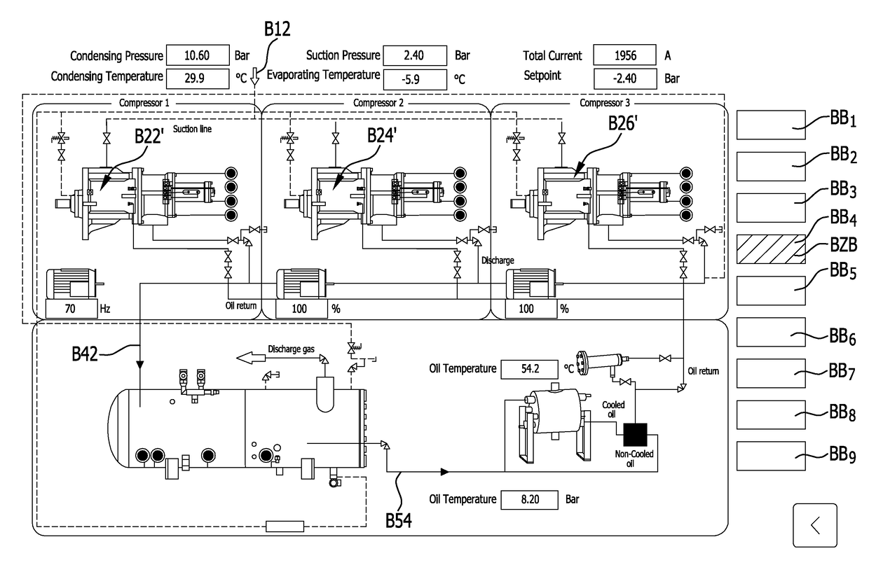
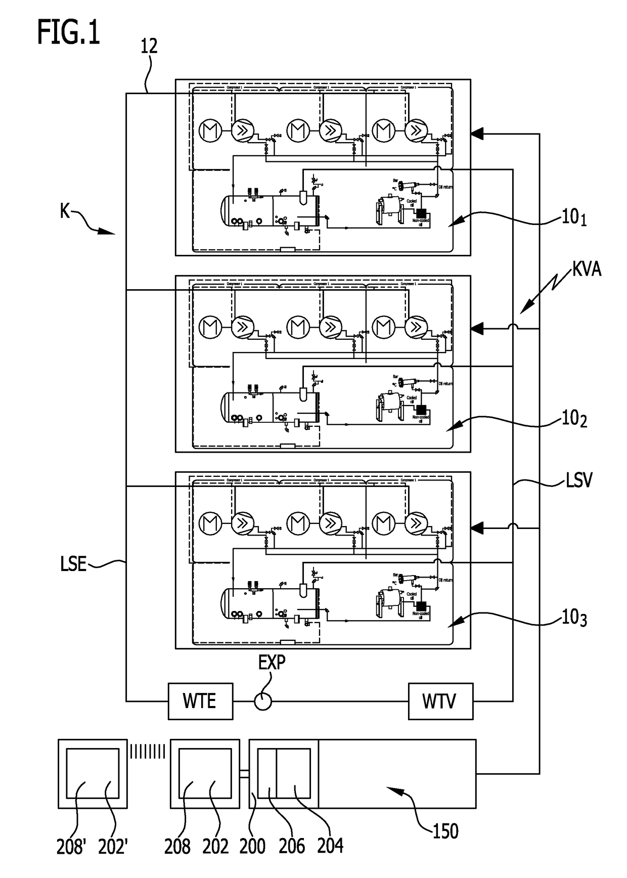
[0124]A refrigerant circuit K that is illustrated schematically in FIG. 1 includes a first line system LSE for expanded refrigerant, a second line system LSV for compressed refrigerant, and a refrigerant compressor system KVA that compresses the expanded refrigerant from the line system LSE and supplies the compressed refrigerant to the line system LSV for compressed refrigerant.

[0125]Further, the refrigerant circuit K also includes a heat transfer device WTV for cooling the refrigerant that has been compressed by the refrigerant compressor system KVA, wherein this heat transfer device is connected to the line system LSV, an expansion member EXP that is arranged downstream of the heat transfer device WTV and expands the compressed refrigerant and supplies it to a heat transfer device WTE in which the refrigerant that has been cooled by the expansion is able to take up heat.

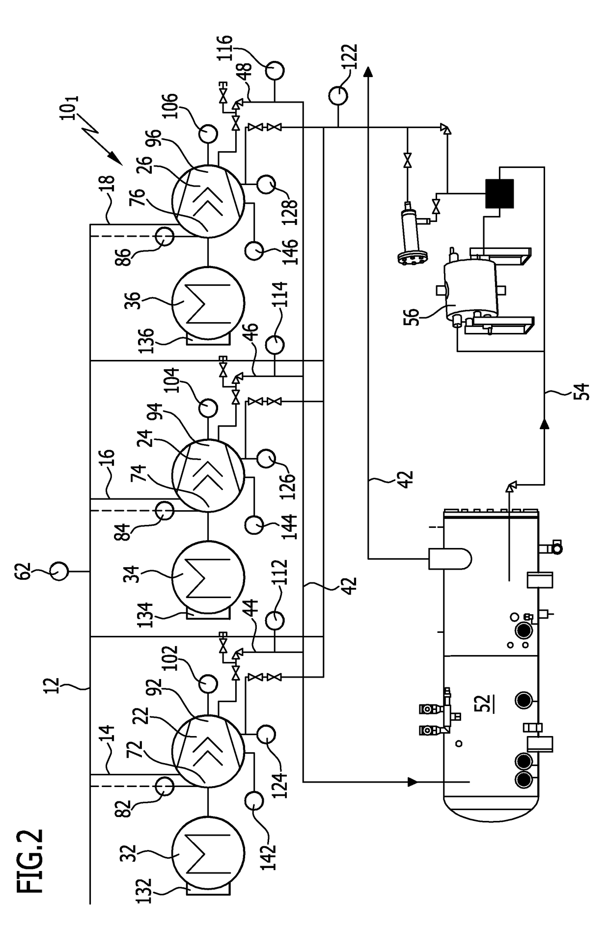
[0126]The refrigerant compressor system KVA that is illustrated by way of example in FIG. 1 for its part includ...


PUM


Abstract

In order to improve a control unit for operating a refrigerant compressor system, wherein the refrigerant compressor system has a first refrigerant line system for expanded refrigerant, a second refrigerant line system for compressed refrigerant, and at least one refrigerant compressor, which operates between the first refrigerant line system and the second refrigerant line system and is driven by its own motor, and wherein the control unit has an operating unit, such that it is operable in a user-friendly manner, it is proposed that the operating unit should have a memory for image element data, for representing at least one component of the refrigerant compressor system, that the operating unit should have a display unit which, using the image element data of the at least one component of the refrigerant compressor system, displays this at least one component on the display unit, as a component image element.

Description

CROSS-REFERENCE TO RELATED PATENT APPLICATION[0001]This application is a continuation of International application number PCT / EP2016 / 054905 filed on Mar. 8, 2016.[0002]This patent application claims the benefit of International application No. PCT / EP2016 / 054905 of Mar. 8, 2016 and German application No. 10 2015 103 729.7 of Mar. 13, 2015, the teachings and disclosure of which are hereby incorporated in their entirety by reference thereto.BACKGROUND OF THE INVENTION[0003]The invention relates to a control unit for operating a refrigerant compressor system, wherein the refrigerant compressor system has a first refrigerant line system for expanded refrigerant and a second refrigerant line system for compressed refrigerant from at least one refrigerant compressor, which operates between the first refrigerant line system and the second refrigerant line system and is driven by its own motor, wherein the control unit has an operating unit.[0004]Control units of this kind are known from the...

Claims


Application Information

Patent Timeline
Patent Type & Authority Applications(United States)
IPC IPC(8): F25B49/02
CPCF25B49/022F25B2400/077F25B2700/00F25B2600/02F25D2400/36
Inventor CHRISTENSEN, FINN
Owner BITZER KUEHLMASCHINENBAU GMBH
Why Eureka
Try Eureka