Safety sign having a safety switch with an integrated light

a safety switch and safety switch technology, applied in the field of building safety, can solve the problems of difficult placement of fdc's and fire hose cabinets, and achieve the effects of less labor, less expensive manufacture, and reduced vandalism

Active Publication Date: 2022-03-22
WRIGGLE STEVE +1
View PDF10 Cites 0 Cited by
  • Summary
  • Abstract
  • Description
  • Claims
  • Application Information

AI Technical Summary

Benefits of technology

[0008]It is the objective of this invention to identify within a building, other such cabinet features containing fire department connection (FDC) valves and fire hose cabinets. In the event of a fire, the fire personnel typically terminate the AC power to fire involved buildings or structures for safety reasons. With a fire emitting large quantities of smoke, locating such FDC's and fire hose cabinets can be made difficult. It is the objective of the etched and edge lit cabinet window, for example etched with “FDC Type I, II or III” in aqua or blue (representing the color of water) enabling firefighters to rapidly locate such cabinets to quickly expedite interior structure fire extinguishment.
[0013]It is another object of the present invention to provide a safety switch with integrated light, which is less expensive to manufacture; reduces vandalism by omitting protruding buttons; requires less labor during test procedures; and provides easier user interface during test procedures; and notifications during failures. Most importantly the object of this invention is to enhance the visibility through a larger and brighter light source through the lit integrated switch to detect failures within emergency lighting fixtures.

Problems solved by technology

With a fire emitting large quantities of smoke, locating such FDC's and fire hose cabinets can be made difficult.

Method used


Image

  • Safety sign having a safety switch with an integrated light
  • Safety sign having a safety switch with an integrated light
  • Safety sign having a safety switch with an integrated light

Examples


Embodiment Construction

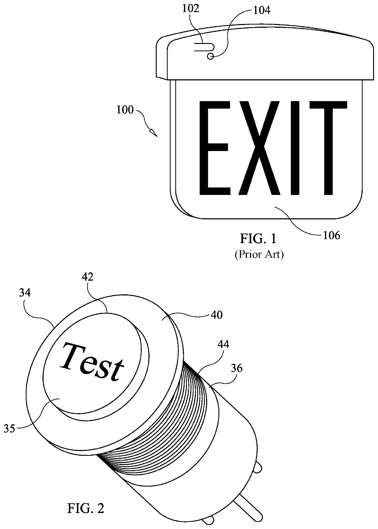
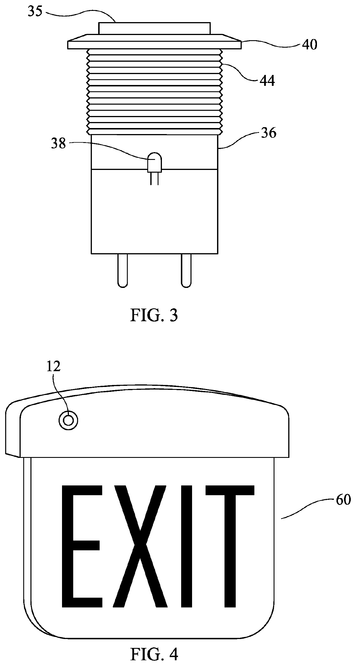
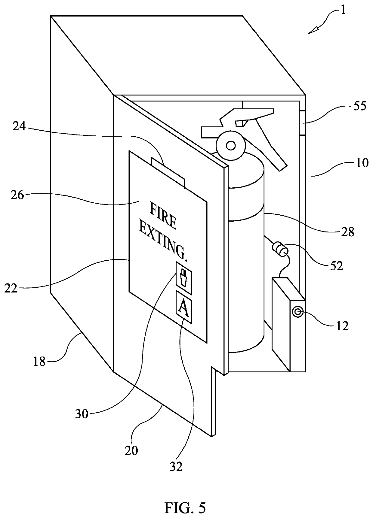
[0023]With reference now to the drawings, and particularly to FIG. 1, there is shown a prior art EXIT sign 100. The prior art exit sign includes a test button 102 and a power indicator light 104. The test button 102 switches electrical power supplied to lighted sign 106 from AC building voltage to a backup battery (not shown). The power indicator light 104 is illuminated as long as the lighted sign 106 is being supplied with power from the AC building voltage. With reference to FIGS. 2, 5 and 6, a safety device cabinet 1 includes an equipment cabinet 10, a safety switch having an integrated light 12, a switch logic circuit 14 and a battery back-up 16. The safety device cabinet 10 includes an equipment cabinet 18 and an access door 20. The access door 20 includes a window 22 and an edge light emitting device 24. The window 22 is etched with a message26 containing a description of the equipment, such as a fire extinguisher 28 stored in the equipment cabinet 10. The window 22 may be fa...


PUM

PropertyMeasurementUnit
electrical poweraaaaaaaaaa
AC voltageaaaaaaaaaa
DC voltageaaaaaaaaaa

Abstract

A safety device cabinet includes an equipment cabinet, a safety switch having an integrated light, a switch logic circuit and a battery back-up. The safety device cabinet includes an equipment cabinet and an access door. The access door includes a window and an edge light emitting device. The window is etched with a message containing a description of the equipment stored in the equipment cabinet. The safety switch with an integrated light includes a push momentary switch, a light bezel and a bezel light source. An inner perimeter of the outer shell is sized to receive a push button of the push momentary switch. The light bezel preferably includes an opening to receive a light emitting portion of the light source. The switch logic circuit preferably includes a AC to DC converter, a microprocessor, a software program and a monitoring device.

Description

CROSS-REFERENCES TO RELATED APPLICATIONS[0001]This is a divisional patent application, which takes priority from patent application Ser. No. 17 / 344,137, filed on Jun. 10, 2021.BACKGROUND OF THE INVENTIONField of the Invention[0002]The present invention relates generally to building safety and more specifically to a safety sign having a safety switch with an integrated light.Discussion of the Prior Art[0003]Emergency lighting, such as Exit signs have been mandated for one hundred years (1911), since the New York Triangle Shirtwaist factory fire that killed 146 people, mostly women and children. The National Fire Protection Association (NFPA) is an organization that institutes codes and standards applicable to national, state, and local laws. The NFPA has required that all EXIT signs be lit all the time since 1911 and emergency lighting fixtures be lit during AC power failures. During this one-hundred-year period, the lighting required to support emergency lighting fixtures includes E...

Claims


Application Information

Patent Timeline
Patent Type & Authority Patents(United States)
IPC IPC(8): G09F13/22F21S9/02H01H13/52F21V23/02F21V8/00A47B96/00F21V3/06A47B81/00F21W111/00
CPCF21S9/022A47B81/00A47B96/00F21V3/062F21V23/02G02B6/006G09F13/22H01H13/52F21W2111/00G02B6/0095H01H9/182H01H13/023H01H2219/0622H01H2300/054
Inventor WRIGGLE, STEVEWRIGGLE, DOROTHY J.
Owner WRIGGLE STEVE
Why Eureka
Try Eureka