Apparatus, method, and system for a multi-part visoring and optic system for enhanced beam control

a multi-part visoring and beam control technology, applied in lighting applications, lighting support devices, lighting and heating apparatuses, etc., can solve the problems of poor lighting design, large quantity of light not a benefit, and insufficient luminous density lighting fixtures, etc., to achieve improved beam control

Active Publication Date: 2018-01-11
MUSCO
View PDF1 Cites 4 Cited by
  • Summary
  • Abstract
  • Description
  • Claims
  • Application Information

AI Technical Summary

Benefits of technology

[0007]Applications in the area of precision lighting design—such as sports lighting—benefit from a concerted, synergistic effort insomuch that beam control is improved when all light directing and redirecting devices are considered together, and insomuch that adverse lighting effects are best avoided when considering how all the lighting fixtures in an array interact with one another.
[0012]b. maximized useful light (i.e., directed, redirected, or otherwise controlled so to place light in a desired location) by improved visor design;
[0013]c. minimized undesirable lighting effects (e.g., beam shift, shadowing, center beam shift, etc.) through a combination of said improved optic and visor design; and
[0014]d. minimized onsite and / or offsite glare through a combination of said improved optic and visor design so to effectuate improved beam control.

Problems solved by technology

Focusing on such precise lighting applications, there are a number of issues in the art.
Of course, a luminously dense lighting fixture is not in and of itself entirely adequate for such lighting applications; a large quantity of light is not a benefit if it is not controlled in a precise manner.
When maximum candela (or photometric center) is shifted so much (e.g., due to excessive pivoting of a visor) that shape and / or distribution is perceivably impacted, issues arise; in this sense, such shifting of the center beam is a bellwether for poor lighting design.
If the virtual center beam and the actual center beam do not match up when the actual product is installed and aimed, then beam patterns will not overlap as intended (resulting in, e.g., dark spots) and distribution will be off (resulting in, e.g., violation of lighting uniformity requirements in the specification); and generally speaking, beam control will not be maintained.
Currently a piecemeal approach is often taken to provide some degree of beam control in precision lighting design: higher efficacy light sources might be paired with a relatively inefficient luminaire housing, a visor might be added after the fact due to perceived glare but doing so results in a decrease in overall light levels, so then the light sources might be driven harder to compensate thereby reducing what was previously a high efficacy, and the compensation cycle continues.

Method used


Image

  • Apparatus, method, and system for a multi-part visoring and optic system for enhanced beam control
  • Apparatus, method, and system for a multi-part visoring and optic system for enhanced beam control
  • Apparatus, method, and system for a multi-part visoring and optic system for enhanced beam control

Examples


embodiment 1

B. Exemplary Method and Apparatus Embodiment 1

[0043]A more specific exemplary embodiment for improved beam control, utilizing aspects of the generalized example described above, will now be described. The present embodiment addresses issues common in the art of precision lighting design—namely, fixture interaction within an array, avoiding undesirable lighting effects, and providing onsite and / or offsite glare control—in a lighting fixture designed to be luminously dense with sharp beam cutoff; this is achieved through a multi-part visoring and optic system which is presently discussed.

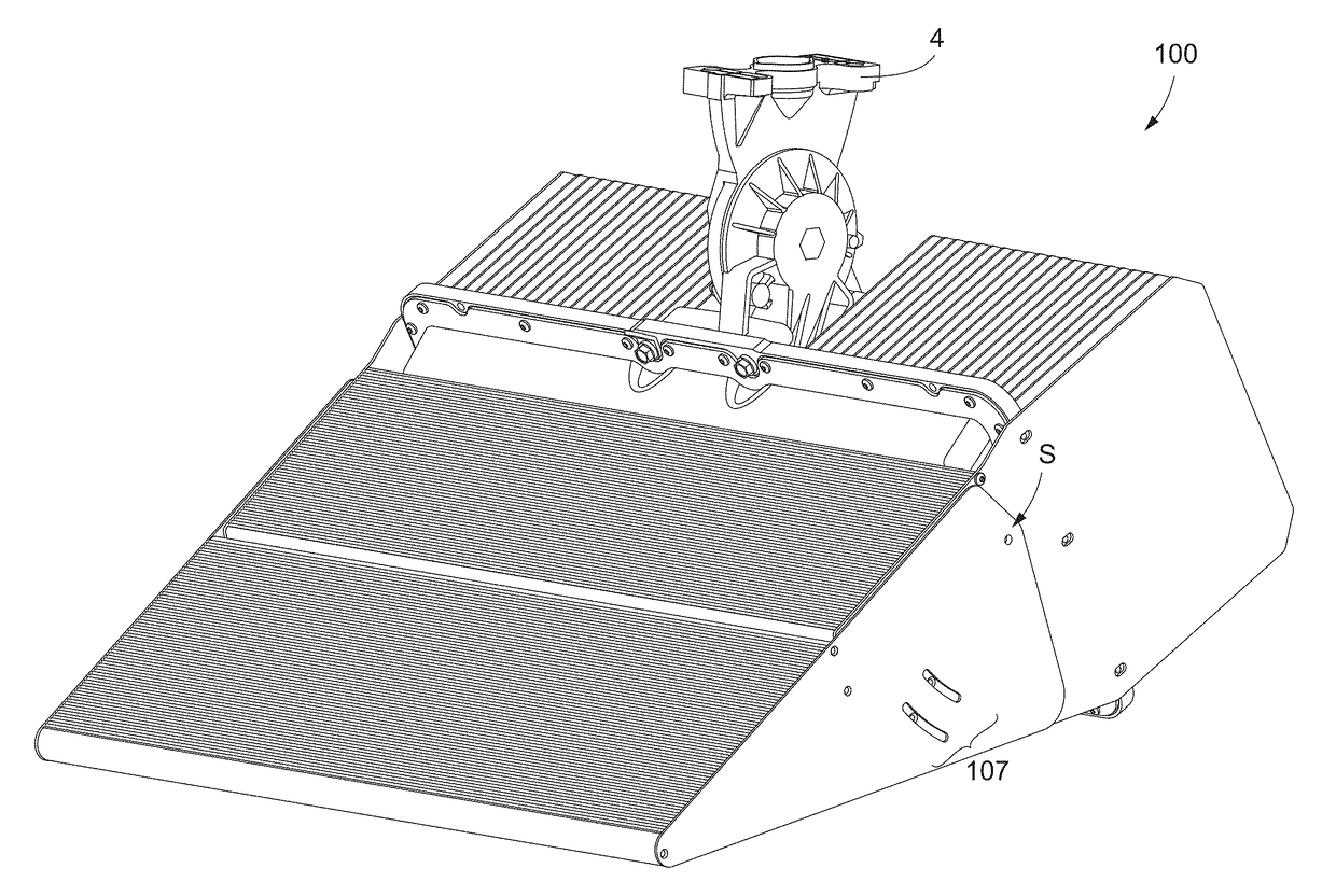
[0044]Ribbing on External Visor

[0045]As previously stated, offsite glare can occur when light from a lighting fixture higher in an array of lighting fixtures strikes the top of a lighting fixture lower in the array of lighting fixtures. As such, state-of-the-art LED lighting fixture 80 is modified so to include ribbing on top side 85 of visor 83; the result is LED lighting fixture 90 of FIGS. 4A and B...


PUM


Abstract

Precision lighting design is a subcategory of lighting design which benefits from a concerted, synergistic effort to improve beam control; sports lighting is one such example. Beam control is improved when all light directing and redirecting devices are considered together, and insomuch that adverse lighting effects are best avoided when considering how all the lighting fixtures in an array interact with one another. To that end, envisioned is a multi-part visoring (i.e., light redirecting) and optic (i.e., light directing) system designed with consideration towards how a fixture lives in a mounted space—how its photometric and physical presence affects other fixtures in or proximate said space—while demonstrating improved beam control over that which is available to general purpose (e.g., indoor residential) lighting.

Description

CROSS-REFERENCE TO RELATED APPLICATIONS[0001]This application claims priority under 35 U.S.C. §119 to provisional U.S. Application Ser. No. 62 / 359,747, filed Jul. 8, 2016, provisional U.S. Application Ser. No. 62 / 359,931, filed Jul. 8, 2016, and provisional U.S. Application Ser. No. 62 / 405,127, filed Oct. 6, 2016, all of which are hereby incorporated by reference in their entirety.I. TECHNICAL FIELD OF THE INVENTION[0002]The present invention generally relates to improving control of the composite beam issued forth from an elevated and / or aimed lighting fixture containing a plurality of light sources. More specifically, the present invention relates to avoiding undesirable lighting effects in said lighting fixture while still providing desired beam cutoff—perceivable center beam shift—through improved beam control.II. BACKGROUND OF THE INVENTION[0003]Generally speaking, lighting is designed to adequately light a target area from some distance. However, there are some lighting applic...

Claims


Application Information

Patent Timeline
Patent Type & Authority Applications(United States)
IPC IPC(8): F21V13/04F21V5/00F21V21/30F21V14/04F21V7/00F21W131/105F21W131/407
CPCF21V13/04F21V21/30F21V5/007F21V7/0066F21Y2105/16F21Y2115/10F21W2131/407F21W2131/105F21V14/04F21V11/183F21V11/00F21V15/01F21V17/02F21W2131/10
Inventor GORDIN, MYRONDEBOEF, JOEL D.HEATON, STEVEN T.LICKISS, CHRIS P.MCKEE, LUKE C.
Owner MUSCO
Why Eureka
Try Eureka